Difference between revisions of "Chief Architect X12 - EN"
(→Layouts) |
|||
| (5 intermediate revisions by the same user not shown) | |||
| Line 1: | Line 1: | ||
| − | = Introduction = | + | =Introduction= |
The basic approach is completely different than in autocad. The whole software was invented to design residential buildings in it, not a universal CAD design program. (Computer-aided design). The big difference is that the rendered 3D image is created while drawing, unlike in autoCad. Every detail of the software is made up of building design, not drawing a building in it would be very difficult. | The basic approach is completely different than in autocad. The whole software was invented to design residential buildings in it, not a universal CAD design program. (Computer-aided design). The big difference is that the rendered 3D image is created while drawing, unlike in autoCad. Every detail of the software is made up of building design, not drawing a building in it would be very difficult. | ||
| Line 12: | Line 12: | ||
<hr> | <hr> | ||
| − | Using the GUI | + | =Using the GUI= |
== Overview == | == Overview == | ||
| Line 582: | Line 582: | ||
<br> | <br> | ||
<hr> | <hr> | ||
| − | Windows and doors | + | = Windows and doors = |
== Windows == | == Windows == | ||
| Line 1,096: | Line 1,096: | ||
This will now be the latter two. | This will now be the latter two. | ||
<br> | <br> | ||
| − | == What are materials == | + | == What are the materials == |
Materials play a very important role even in invisible components for two reasons: | Materials play a very important role even in invisible components for two reasons: | ||
* In the final, exact list of materials, non-visible elements are also included (concrete base, wooden frame, OSB covering, etc.) | * In the final, exact list of materials, non-visible elements are also included (concrete base, wooden frame, OSB covering, etc.) | ||
| Line 1,114: | Line 1,114: | ||
: [[File: ClipCapIt-210529-004133.PNG]] | : [[File: ClipCapIt-210529-004133.PNG]] | ||
| − | Material types | + | == Material types == |
Interestingly, our settings can only be viewed by mothers in the 'User catalog'. It either gets material here by creating a new one or copying an existing one and then we can put it in here. | Interestingly, our settings can only be viewed by mothers in the 'User catalog'. It either gets material here by creating a new one or copying an existing one and then we can put it in here. | ||
: [[File: ClipCapIt-210529-004354.PNG]] | : [[File: ClipCapIt-210529-004354.PNG]] | ||
| Line 1,148: | Line 1,148: | ||
<br> | <br> | ||
| − | OSB material (a good | + | == OSB material (a good example) == |
OSB also has three resources in the 'Library browser': | OSB also has three resources in the 'Library browser': | ||
: [[File: ClipCapIt-210529-183518.PNG]] | : [[File: ClipCapIt-210529-183518.PNG]] | ||
| Line 1,174: | Line 1,174: | ||
<br> | <br> | ||
<br> | <br> | ||
| − | Production of custom objects and shapes (Symbol) == | + | ==Production of custom objects and shapes (Symbol) == |
=== Overview === | === Overview === | ||
As you can see, there are both 2D and 3D objects in the built-in factory library. As I understand it, 2D objects are always used by extrusion in CA. For example, if we have a 2D object of this shape, we can turn it into such a 3D window sill automatically: | As you can see, there are both 2D and 3D objects in the built-in factory library. As I understand it, 2D objects are always used by extrusion in CA. For example, if we have a 2D object of this shape, we can turn it into such a 3D window sill automatically: | ||
| Line 1,886: | Line 1,886: | ||
<hr> | <hr> | ||
| − | Tips and Tricks | + | = Tips and Tricks = |
== Deck before external insulation == | == Deck before external insulation == | ||
| Line 1,914: | Line 1,914: | ||
<br> | <br> | ||
<br> | <br> | ||
| − | Balcony beam and columns | + | == Balcony beam and columns == |
In the picture below, half of the balcony is in the air and there is a terrace below: | In the picture below, half of the balcony is in the air and there is a terrace below: | ||
: [[File: ClipCapIt-210425-234714.PNG]] [[File: ClipCapIt-210425-234800.PNG]] [[File: ClipCapIt-210425-235028.PNG]] | : [[File: ClipCapIt-210425-234714.PNG]] [[File: ClipCapIt-210425-234800.PNG]] [[File: ClipCapIt-210425-235028.PNG]] | ||
| Line 1,953: | Line 1,953: | ||
<br> | <br> | ||
| − | == OSB | + | == Balcony with OSB cover == |
: [[File: ClipCapIt-210408-234734.PNG]] [[File: ClipCapIt-210425-233535.PNG]] | : [[File: ClipCapIt-210408-234734.PNG]] [[File: ClipCapIt-210425-233535.PNG]] | ||
| Line 1,983: | Line 1,983: | ||
<br> | <br> | ||
| − | + | == Sloped wall + straight railing around the balcony == | |
There are things you can't do with a built-in feature in CA. In this case, we have to improvise or model the given shape by hand. Eg the corner railing element shown in the picture below with the sloping wall, but above it the straight railing cannot be solved with the built-in tools. '' 'Bold text' '' | There are things you can't do with a built-in feature in CA. In this case, we have to improvise or model the given shape by hand. Eg the corner railing element shown in the picture below with the sloping wall, but above it the straight railing cannot be solved with the built-in tools. '' 'Bold text' '' | ||
: [[File: ClipCapIt-210408-213101.PNG]] | : [[File: ClipCapIt-210408-213101.PNG]] | ||
| Line 2,024: | Line 2,024: | ||
<br> | <br> | ||
<br> | <br> | ||
| + | |||
== Stone fence with garden gate == | == Stone fence with garden gate == | ||
Here is the full step-by-step description: https://www.chiefarchitect.com/support/article/KB-00874/placing-a-gate-in-a-terrain-wall.html | Here is the full step-by-step description: https://www.chiefarchitect.com/support/article/KB-00874/placing-a-gate-in-a-terrain-wall.html | ||
| Line 2,048: | Line 2,049: | ||
: [[File: ClipCapIt-210521-210018.PNG]] | : [[File: ClipCapIt-210521-210018.PNG]] | ||
<br> | <br> | ||
| − | == | + | == Outer wall cover hangs below the button plate == |
=== What we want === | === What we want === | ||
: [[File: ClipCapIt-210521-210704.PNG]] | : [[File: ClipCapIt-210521-210704.PNG]] | ||
| Line 2,085: | Line 2,086: | ||
| − | + | == Custom ceiling above paved doorway == | |
{{note | You don't have to do everything from CA 'smart' objects. Use simple boxes if you get stuck and then extract the figure from the CAD detail drawing. I suffered the most with this because I wanted to solve it all with a CA ceiling. The bottom cover of the I-beam is finally a 3D box smoothly!}} | {{note | You don't have to do everything from CA 'smart' objects. Use simple boxes if you get stuck and then extract the figure from the CAD detail drawing. I suffered the most with this because I wanted to solve it all with a CA ceiling. The bottom cover of the I-beam is finally a 3D box smoothly!}} | ||
: [[File: ClipCapIt-210522-202236.PNG]] [[File: ClipCapIt-210521-220656.PNG]] [[File: ClipCapIt-210522-203836.PNG]] | : [[File: ClipCapIt-210522-202236.PNG]] [[File: ClipCapIt-210521-220656.PNG]] [[File: ClipCapIt-210522-203836.PNG]] | ||
| Line 2,234: | Line 2,235: | ||
This is necessary in order to be able to give it a different floor structure than the living room has. | This is necessary in order to be able to give it a different floor structure than the living room has. | ||
| − | === The walls run down to the | + | === The walls run down to the basement === |
: [[File: ClipCapIt-210528-235935.PNG]] | : [[File: ClipCapIt-210528-235935.PNG]] | ||
Care must be taken that the three walls shown in the picture do not go all the way down to the basement, only to the ground floor. To do this, do two 'Cross sections', then grab the bottom of the walls and pull them to the desired height up to the ground floor level: | Care must be taken that the three walls shown in the picture do not go all the way down to the basement, only to the ground floor. To do this, do two 'Cross sections', then grab the bottom of the walls and pull them to the desired height up to the ground floor level: | ||
| Line 2,241: | Line 2,242: | ||
| − | === Sloping wall | + | === Sloping wall in the stairwell === |
: [[File: ClipCapIt-210529-000540.PNG]] | : [[File: ClipCapIt-210529-000540.PNG]] | ||
The CA can follow the wall with the ladder at the edges of the stairs, but not between the two steps. That’s why I put the triangle on top of a 3D box that I covered with the wall material. | The CA can follow the wall with the ladder at the edges of the stairs, but not between the two steps. That’s why I put the triangle on top of a 3D box that I covered with the wall material. | ||
| Line 2,251: | Line 2,252: | ||
<br> | <br> | ||
| − | Terrain = | + | = Terrain = |
https://www.chiefarchitect.com/videos/watch/75/terrain-site-plan-basics.html?playlist=101 <br> | https://www.chiefarchitect.com/videos/watch/75/terrain-site-plan-basics.html?playlist=101 <br> | ||
| Line 2,352: | Line 2,353: | ||
| − | Draw a terrain | + | == Draw a terrain == |
Go to the 'Terran Configuration' toolbar ([[File: ClipCapIt-210428-000840.PNG]]) in the top right corner of the toolbar and select the 'Create terrain perimeter' tool from the 'Terrain tool': | Go to the 'Terran Configuration' toolbar ([[File: ClipCapIt-210428-000840.PNG]]) in the top right corner of the toolbar and select the 'Create terrain perimeter' tool from the 'Terrain tool': | ||
: [[File: ClipCapIt-210428-001122.PNG]] | : [[File: ClipCapIt-210428-001122.PNG]] | ||
| Line 2,560: | Line 2,561: | ||
| − | Layout overview | + | == Layout overview == |
=== Create === | === Create === | ||
The layout is always created from a layout template. Then we can send different views of the plan to any page of the layout. You can create multiple layouts for a plan. The layout is an independent file that we saved separately to the plan, so it is not part of the plan file. That is, every decent project contains at least one plan and one layout extension file, and the plan and layout live separately. | The layout is always created from a layout template. Then we can send different views of the plan to any page of the layout. You can create multiple layouts for a plan. The layout is an independent file that we saved separately to the plan, so it is not part of the plan file. That is, every decent project contains at least one plan and one layout extension file, and the plan and layout live separately. | ||
Latest revision as of 16:07, 28 August 2021
Contents
- 1 Introduction
- 2 Using the GUI
- 3 Building tools
- 4 Wall and railing tools
- 5 Windows and doors
- 6 Roofing plan
- 7 Ceiling plan
- 8 Foundtaion
- 9 Materials and symbols
- 10 Framing
- 10.1 Introduction
- 10.2 Generate wall framing
- 10.2.1 Basics
- 10.2.2 Framing generation on a wall
- 10.2.3 Changing Framing Manually
- 10.2.4 Disable Framing
- 10.2.5 Automatic blocking
- 10.2.6 Framing schedule
- 10.2.7 Side view with framing
- 10.2.8 Wall framing labels
- 10.2.9 Modifying Corner Encounters
- 10.2.10 Delete wall framing
- 10.2.11 Framing reference
- 10.2.12 Balloon framing
- 10.2.13 Rainscreen 1
- 10.2.14 Rainscreen 2
- 10.3 Ceiling framing
- 10.4 Floor framing
- 10.5 Windows and doors
- 10.6 Roof trusses
- 11 Schedules
- 12 Troubleshooting
- 13 Tips and Tricks
- 13.1 Deck before external insulation
- 13.2 Balcony beam and columns
- 13.3 Balcony with OSB cover
- 13.4 Sloped wall + straight railing around the balcony
- 13.5 Stone fence with garden gate
- 13.6 Steel I-beam + cushion trees
- 13.7 Outer wall cover hangs below the button plate
- 13.8 Custom ceiling above paved doorway
- 13.9 Stairs in front of the entrance
- 13.10 Staircase
- 14 aaaa
- 15 Terrain
- 16 Layouts
- 17 Walkthrough
Introduction
The basic approach is completely different than in autocad. The whole software was invented to design residential buildings in it, not a universal CAD design program. (Computer-aided design). The big difference is that the rendered 3D image is created while drawing, unlike in autoCad. Every detail of the software is made up of building design, not drawing a building in it would be very difficult.
Main characteristics:
- Produces a 3D view even out-of-the box
- the usual blueprints are sharpened for production: floor plan, elevations, sections, site plan, roof plan, ceiling plan, framing plan.
- very rich basic library. it has a lot of furniture and materials in it.
- also produces framing blueprints for roofs, slabs and walls.
- is pointed for the design of timber-framed buildings. Able to calculate how much wood is needed in total for construction.
Using the GUI
Overview
The interface is much simpler than we were used to in AutoCad. Nevertheless, we are facing a very sophisticated, versatile residential and smaller commercial, multi-storey house design program.
Each project is based on a plan file. These are always found in the * .plan file. A plan file is the complete 3D model of a house, so it does not contain layouts, that is, printable blueprints. A * .plan file can be thought of as a model space in AutoCad. From the plan we can create layout files. A * .layout file contains a complete blueprint along with all its pages. We are always working on a specific * .plan file at the same time (model space). When we are done, we can send each element of the model to the currently active layout on the appropriate page, where the model is no longer editable, the layout is treated as a quasi-image. It's just a quasi-image, because if we modify the model in the plan, it will be able to automatically update the view in * .layout, as we'll see.

https://www.youtube.com/watch?v=8B9VBrObzqs
Multiple plan and multiple layout files can be open in the CA at the same time, so we can copy from one to another. These will all appear on a separate tab in the program.

We can send "images" (views) from one plan to multiple layouts, but we typically produce a layout for a plan. The plan and the layouts to which we sent views / images from it will be wired together, there will be a close connection between them. If we change the plan, the pictures and boxes usually change on the layout as well.
Drawings in a plan can only be used in that plan. The transition between plans is provided by the 'Library' using the 'Library browser', where there are elements from the factory and made by us that can be inserted into any plan and layout.
Being a house design program, the basis of everything is the "Working Plan view" in the plan, where you can create a house plan for each level individually, including the roof and foundation, as well as the entire site plan. with appropriate height values. In addition, various page and 3D views are available, where it is also possible to manipulate the model, but the primary "view" for this is the "Working Plan View".
Just like in AutoCad, there are layers here. But here they are given a more important role, or rather we are dealing with completely predefined layers. There are roughly 80 predefined built-in layers in each plan by default. A predefined layer is invented for each type of building element, and each building element is automatically placed on the default layer. The layer determines its visibility, the color, linetype, stitching, etc. of the element in the floor plans. In fact, you don’t really need to create new layers, the built-in 50-80 layers perfectly cover every element of a family home.
An important concept is "View". The CA has 9 built-in views. In each view, we see the model in floor plan view and can modify it. Each factory view has a set of default layer settings that contain the most appropriate layer settings for that view type. With the view option, we actually select a set of layer settings. For example, in "Electrical Plan View" there is no need to display the dimensions, and it is enough to display the walls as just one line, there is no need to hatch or fill the walls.

The appearance of layers can be set separately in each view. And it not only controls whether it looks or not, but also how it is in a particular view, but also how. (stitching, filling, color).
Let's look at the interface elements:
1. View or view selector. The default work space where the building is primarily to be drawn is the 'Workin Plan View' . The viewer selector actually turns it on or redefines it in a predefined way
2. Main Menu Toolbar. These have built-in construction tools. Each contains a submenu, see page 3
3. Tools in a selected main menu toolbar. Eg in the picture the walls tools are selected, here you can choose from different wall categories.
4. Manipulation tools for an object that has already been created and selected in the workspace. There are basic manipulation tools that appear for each object type and some that are specific to a particular object type, such as walls, you can connect walls to it with the "Connect Walls" tool.
5. Select levels. Whether you are in any view or 3D view, here you can choose which level to see. By default, we are at level 1. "A" (Atic) is the attic, while level 0 is the basement.
6. Project browser: All open plans and layouts are shown here.
7.

Views, layers and default sets

Layer
https://www.chiefarchitect.com/videos/watch/5483/understanding-layer-sets.html?playlist=100
There are layers in CA the same as in AutoCad. All l
Layer set
https://www.chiefarchitect.com/videos/watch/5483/understanding-layer-sets.html?playlist=100
... TODO ...
If you rewrite a layer in a layer-set, it will apply permanently, not just to that view (plan view or other camera views). ..
Default set
Note
In the pre-X12 version this was called the Annotation set
The Defult set is a set of properties. There are several object types in a CA that can have multiple default settings, and these default settings allow the CA to switch between different sets to determine which set to load. The Default set (formerly known as Annotions set) groups the properties of a total of 8 elements, all of which are guide lines and text dimensions:
- Dimensions
- Arrow
- Revision cloud
- Notes
- Rich text
- Text
- Markers

The currently selected default set determines in which style and on which layer the phenite 8 object type will be drawn by default. But the default set is not explicitly chosen, but implicit with the 'Saved view', see next section. The list of 'default sets' in the 'default' tool (![]() ) can be opened with 'Default sets':
) can be opened with 'Default sets':

... TODO ...
Saved Veiw
https://www.chiefarchitect.com/videos/watch/2421/saved-plan-views.html#:~:text=2421,walls%20associated%20with%20the%20view. The view is a set of saved settings. When we select a view from the 'Plan views' list, we actually select the following options:

- Leyer set (which layer set is active by defult in the given view)
- Reference display ??
- You can open multiple 2D views at once based on your saved settings
- Floor and zoom specific settings
- also selects 'default set'.
... TODO ...
Reference display
The view also has a 'reference display' setting. The 'reference display' always draws auxiliary objects from another level in the same plan or you can even draw the contour of objects from another plan, which is always helpful for drawing, eg at level 2 if you draw the walls of level 1 walls. contour, we know on the second level inside the room also where to put the walls.
At a given level, you can turn it on in a given plan view with the 'Reference display' button (![]() ) in the menu on the right. If enabled, references set to the current view (eg 'Plot plan view') and the current level will be displayed in the plan view, which by default always uses level and red contours below the current level. In the image below, we are on level 2 and draw the contour of the walls of level 1 in red:
) in the menu on the right. If enabled, references set to the current view (eg 'Plot plan view') and the current level will be displayed in the plan view, which by default always uses level and red contours below the current level. In the image below, we are on level 2 and draw the contour of the walls of level 1 in red:

To open the settings for a view in the 'Project browser':

Then the reference display settings can be found on the third tab:

You can see that if 'Plot plan view' is selected from the view selector drop-down list at the top of the menu bar, it will also bring with it the 'Reference display' settings shown in the image above. There is a red arrow in the bottom row that shows what applies to the current level. The name of the current paln is always listed here.
Above it you can see that all your references will be displayed in this view if the 'Reference display' is on. You can see that the level will be selected automatically (which always means the lower level) and will always use the 'Reference display layer set' to display the walls of the lower levels. You can see that if you open the settings of the 'Reference display layer set' that only a few layers are turned on in it and it all shows a red line.

If you double-click the level selector in the top menu:
The 'Change floor reference' dialog will open, where you can change the reference regardless of the settings of the given view:

The levels already appear in this list above and I don't fully understand how it works
... TODO ...
Project browser
Multiple "plan" and "layout" can be open at the same time. The Project Browser shows all open plans and layouts. Both our plans and layouts have their own folder structure, which can also be reviewed in the Project Browser.

The folders listed here do not exist at the file system level, they are part of the plan or layout files. In these virtual folders, the CA automatically places each view and camera view according to its type, not us deciding where to go. Each plan can be found in the following virtual folder system.
- CAD details
- Cameras: There are several types of camera images in the CA.
- Cross sections:
- Floor levels:
- Plan views:
- Schedules: This is where the window, door, room and other schedulers are placed, which are automatically locked by the program.
- Wall details: If you already have a framing plan for the building (see below) then here you can view and modify the framing plan for each wall individually.
Active layer set
The last tab in the three tab window on the right is 'Active layer display options', which differs from 'Layer display options' in that when you select an object, it will always show only the layers that are apply to a given item. For example, if you select a road, only the layers for the road will appear:

Here we see not only the ones that are turned on, but everything that has to do with the path even when a particular layer is turned off.
Move and resize items
TODO: you can always move with dimensions. Either we have any automatica jeó for us or we hire a new one. Solution B: point to point move.
C: temporary point: https://www.chiefarchitect.com/support/article/KB-01031/positioning-a-cad-block-with-accuracy.html
Drawing an object with the exact size
While drawing the object in one of the views, while holding down the left mouse button, press TAB:

The 'Enter coordinates' dialog will appear.

Here you can enter the exact relative and absolute size of the given object.
Free movement of an object along two axes
We are in any view, when you start moving, that is, when you move the mouse over the square in the middle of the selected object, and the mouse changes to four arrows and you start moving with the left mouse:

Then if you press Ctrl next to it, you can move freely in all directions even though all kinds of 'Snap' can be turned on.
Resize object to exact size
If you have a selected object, you will start resizing it while the mouse is pressed, if you press the TAB, the 'Enter coordinates' dialog will open only when you draw a new one:

Move deck relative to wall
The picture below shows a deck next to a wall and we want to move the deck out of the wall:


To do this, zoom in on the wall-deck meeting in plan view, then drag in a 'Point to Point dimension':


Then select the 'Room divider' type side of the deck that makes up the deck. Move the mouse over the dimension number, it will change to a small hand, indicating that it can be overwritten. If we rewrite this here to 10, it will move the wall of the deck relative to the wall. So it always moves the active element relative to the inactive element between which the dimension line is.


Copying and moving an item
If all items are selected, you can copy or move them using the 'Transform / Replicate object' (![]() ) tool in the bottom menu by entering exact numbers along all axes.
) tool in the bottom menu by entering exact numbers along all axes.

In the dialog that opens, you can copy, move, resize, and mirror the object at the same time, depending on which options you check, whether they can be all at once or in multiple copies.

For the rectangle above, we checked to make 3 copies that you would always move 400mm from the previous one. The end result is as follows:

Multiple copy
There is also a separate tool specifically for making multiple copies, which is also available in the bottom menu after selecting the item. 'Multiple copy' (![]() )
)
If you click and hover the mouse over the selected object, the 'Multiple copy' icon will appear above the object, indicating that bulk copying can begin. After clicking on which axis (even diagonally) we start to drag the mouse by holding it down to start making copies at even distances according to the settings.

The allocation distance can be opened in the lower submenu of Multiple Copy with the middle icon: ![]()
This is so much more than 'Transform / Replicate object' that here we can set distances for each object type (say once at the beginning of the project) and depending on what element we make evenly distributed copies of, it will allocate the distance between copies according to the settings.

We can see that there is a General object type that is roughly the same as the 'Copy' function of the 'Transform / Replicate object' tool, only so it is faster. In addition, there are separate Truss, rafter, beam and wall studs.
'Alternate behavior / Secondary offset) is not very important. Some features have alternative settings, and when you switch to alternative mode, the alternative settings always take effect, I don't think that makes much sense. The alternative mode can be switched on and off in the menu item 'Edit -> Edit behaviors -> Alternate'.

Point to Point Move
An object can be moved in a given plane by moving its point precisely to the point of another object. To do this, select the 'Point to point move' (![]() ) tool from the bottom menu for the selected object.
You can then select a point of the object you want to move (Mark A) and click:
) tool from the bottom menu for the selected object.
You can then select a point of the object you want to move (Mark A) and click:

Then you need to select a point of an external object (notation B)

Then click. You will then move the first object along the selected point:

Rotate around custom point
Items can be rotated with the small triangle next to them, where when you move the mouse towards it, it turns into a circle arrow:


Or we can rotate them by specifying the exact degree using the 'Transform / Replica object' tool (![]() ) in the bottom menu:
) in the bottom menu:

Whichever method you use, by default you will use the center of the CAD object as the axis. It is also possible to specify a custom point for rotation. The use of the custom center point can be enabled in the menu item 'Edit -> Edit behavior -> Rotate / Resize around current point'. When enabled, the mouse pointer changes to a small box with an arrow indicating that the feature is enabled:
Custom points can be added with the 'Place Point' in the top toolbar 'Point tools' ( ) (
) (![]() )
)
Put the point somewhere, then a little X will appear there. From now on, all objects will rotate around this. If there are more than one, what is closer will matter:
Point to point resize
For pictures (Picture type), it is possible to resize the picture along two points. When we insert an image, its size is random compared to its model, depending on how cluttered we are in the view. If there are two fixed points in the image, the distance of which is known (e.g. in the case of floor plans we know the length of the pages in the drawing) then the image can be resized along them to fit the model space perfectly. WORKS ONLY FOR PICTURE TYPE !! We select two arbitrary points in the image and tell the CA how far apart those two points will be, and then resize the image proportionally.
Warning
Important that 'Point to point resize' can only be done until you resize or rotate the image, then give false dimensions
Use COPY-PAST to insert an image into one of the plan views. The picture shows a plot map detail. Select the 'Picture' type:

You can see that the size of all the pages is known. Now select the image and select the 'Point to Point resize' (![]() ) tool from the bottom menu.
The mouse pointer then changes to a letter 'A' to select the first point of the section used for resizing.
) tool from the bottom menu.
The mouse pointer then changes to a letter 'A' to select the first point of the section used for resizing.
 This can be a drawing in the picture, but it can also be one end of any line. However, this resizing line can only move at right angles, so if the two points in the image are not in the same line, as in the image above, you will first need to create an auxiliary line that will provide the reference.
Draw a CAD line between one of the two corners of the plot drawing:

Then open the line settings and set 'Angle' to 0 on the 'Line' tab to get a horizontal line with a good reference for resizing:


Now select the image and click on the 'Point to point resize' tool and click on 'A' at one end of the line, then the mouse pointer will change to 'B', click on the other end of the horizontal line, then the reference line will appear. and the sizing windows open:

Enter the exact desired distance between the two points here. We know from the blueprint that it is exactly 34.06 meters. Enter '34 .06 m ', then check' Retain aspect ratio 'and OK. Then the point of the image will be such that the desired distance between the two points will be:
Select items
Select items with tab
Select items of the same type with a shif
Select items of the same type with the 'Select similar' tool
Deselect items
(eg deleting roof plan or framing ...)
Manipulating items
Fillet and Chamfer Tools
https://www.chiefarchitect.com/videos/watch/5310/fillet-and-chamfer-tools.html?playlist=97
You can use the Fillet and Chamfer tools to round or tap CAD corners. To use them, the first step is to select a CAD rectangle:

then select one of the 'Fillet' or 'Chamfer' (![]() ) tools in the bottom menu. In the example, I will show 'Fillet', the other works the same way.
) tools in the bottom menu. In the example, I will show 'Fillet', the other works the same way.
If you select the 'Fillet' tool, its submenu will appear, where you can choose to round only 1 corner or all corners:

The radius of the rounding must always be specified with 'F' (left: 'Set fillet radius') even if all corners are later rounded at once with 'A'. 'Set fillet radius' opens the radius entry dialog:

Enter the desired radius here and click OK. Then nothing will happen yet. We have two options:
'1. Round a corner: '
- Click on the 'Stick mode' pin in the bottom sub-menu (
 ) If it has a small check mark on it, it is on.
 - Then, in the first step, select one of the edges next to the corner you want to round
- click on the corner. Then the edge will round off:

'2. Round all corners: '
After setting the radius, click on 'Set fillet radius' marked 'A'. At this point, it will round all corners:

Trim and Extend Commands
https://www.chiefarchitect.com/videos/watch/306/using-the-trim-and-extend-commands.html
Section / Elevation
Introduction
As we are used to in a CA, all cross sections and elevations are based on the same object type with only different settings. We can produce one from the other by configuration. The Elevation differs from the section only in that one is inside the building. Blackclipped corssesion differs from normal corss esion only in that its depth is limited. The sign of a corss esion is always a small triangle with a circle:
-
 (this is called a callout)

The triangle shows in which direction the elevation or section was drawn. Each elevation has a view where you can see either a facade of the house or a section. You can also save these elevation and cross section views and send them to one of the pages in a layout.
The elevation and section give you the different page views you get in AutoCad in the model space for editing.
The cross section and elevation have the same Specification dialog as all other object types. But here double click doesn't work because it opens the view for elevation. Instead, you can use the Specifcaiton button (![]() ) to open the dialog.
) to open the dialog.
'General tab:'

- Name: This name will appear on the floor-plan during the callout on the one hand and on the layout on the other hand if the section or elevation view is sent to a layout.
- Rendering technique: How to render the view. 'Vector view' can be called a standard.
- Show shadow: Adds shadows to the building based on the current day position. (See Setting lights and sun)
- Edge smoothing: this will give you a softer image
'Plan display' :
How to display the section mark on the floor paln

- Display on all floors: if unchecked, it will only be displayed at the current level.
- Display as callout: this will cause the arrow and circle to appear with the number:
- Placement: where to place the heart + arrow combo and how many of it should be. In the case of an elevation, the 'Center' is good, then it will only put one facing the building, in the case of a section, select 'Both sides' to lay out two, which encloses the secion.
- Callout label: this is important, it will identify the layout to which Elevation or belongs to section. This number is automatically generated by the CA. Prefixed with 'S' for Section and 'E' for Elevation.
- Text below line: The circle can be divided in two and there can still be a text below the view number. If 'Automatic' is checked, it will automatically populate the page number when sent to a layout.
Elevation
Auto generate elevations
Cross section
https://www.chiefarchitect.com/videos/watch/16/cross-section-elevation-views.html?playlist=102
You can make a complete building section with the 'Cross section / Elevation' tool:
If the camera is placed inside the building, it will make a section. The baseline of the section will be the line of the 'Cross section' tool and will look where the dashed arrow points. It doesn't matter the length of the dashed line, it's just the direction.

This will create a section view on a separate tab that goes through the entire building, which is a fully constructive view for the model. We can manipulate any object that has not been cut in half by the section.

You can save the new view in Tools -> Active view -> Save Active view.

The icon is also displayed in the upper left corner in front of the view selector: ![]()
After saving, the new section will be added to the Project Browser in the 'Cross section' virtual folder:

The cross section can also be decorated with arrows, dimensions, and other CAD objects.
You can create an arrow with the 'Leader line' : ![]()

Or you can decorate the drawing automatically with insulation and other materials with the 'Auto Detail' (![]() ) button.
) button.

All changes made in the cross-section are implemented on the entire model!
The cross section should be marked with two callouts, which shows how far from the section the section extends. To do this, open the section Specification dialog with the small blue door and check Both side 'in the' Plan Dispaly '/ Placement box. The 'Cross section line style' will also be active, where the line type can also be set:

Backclipped cross section
The 'normal' cross section tool does not limit in depth and width what we see, no matter how far we draw a dashed line perpendicular to the base line, it only selects the direction and will display everything up to the edge of the model that is only visible from that line, which we marked with the baseline.
In contrast, you can use the 'backclipped cross section' tool (![]() ) to adjust the depth and width both inside and outside the building. Objects will only be visible to the depth until we draw the dashed line. And only as long as the base line lasts.
) to adjust the depth and width both inside and outside the building. Objects will only be visible to the depth until we draw the dashed line. And only as long as the base line lasts.
A good example of how to use this is when you want to show elevation to framing. Then, if we didn’t limit the depth that the view shows, all the back wall vases would hang in the picture. But if we limit the depth to the thickness of the wall, nothing will hang in the picture.
If we start pulling toward the wall outside the building but stop at the wall, the protrusions that are deeper than that wall will no longer be visible. In the figure below, the depth of the dashed line only reaches the corner of the building (this is also indicated by an auxiliary line perpendicular to the dashed line)

In the resulting Elevation view (left) we can see that the left wing of the building is missing. In contrast, a full Elevation veiw would also show the left wing (right figure)


The same is true if used inside the building to make engravings. Only what the line reaches will be visible.
The backclipped cross section differs from the normal cross section only in that the 'General -> Options -> Back clipp after' section is filled in your settings, which tells you how far the section will be displayed from the baseline:

If you also check the 'Clip to slide' option, you will also restrict laterally along the baseline what the section will show. If you check this, a scaling gray small view will appear at both ends of the baseline, which you can also drag to select the width of the section.

As you can see in the image below, the section is limited in both depth (we don’t see the opposite wall and door) and width (we only see this one room):

Stepped section view
https://www.youtube.com/watch?v=SdB1BrYtJd4 (starting at 1:10 p.m.)
The backclipped cross-section baseline can be broken and the individual sections can be shifted relative to each other, in which case we can make a blackcipped cross section that follows, for example, the wall line. To do this, you need to create a balcklipped section line where you turn it on so that the callout is at both ends:

Then use the break tool (![]() ) to cut the baseline where you want it:
) to cut the baseline where you want it:

After the cut, a small gray diamond appears at the cut location, and a gray dot appears on each side of the cut, allowing you to move the two sections independently:

And here is the end result:

3D section
https://www.chiefarchitect.com/support/article/KB-00631/using-the-cross-section-slider.html
We can also make a 3D section of the building. To do this, create a 'Perspective full overview' : ![]() Rotate the model to the desired angle because you cannot rotate while making the section.
Rotate the model to the desired angle because you cannot rotate while making the section.
Then select 3D -> Camera view options -> Cross section slider:

A slider dialog will appear where you can cut out of the building along all directions.

After the cut, we can rotate the already cut model again:

Section to CAD conversion
https://www.chiefarchitect.com/videos/watch/5479/creating-fully-editable-cross-sections.html?playlist=102
Sections and elevation views can be converted to 2D CAD detail drawing. To do this, select 'CAD -> CAD detail from view'. :

Then a 2D, black and white CAD drawing will be created from the previous model, which will be completely detached from the model, all its elements will be editable in two lines, and if the model changes it will no longer follow this, it will be a standalone 2D CAD detail drawing:

It will be included in 'CAD details' in Project Brower. We can rename it and after manipulation we can also send it to a layout. The standard CAD toolkit can be manipulated.
Reference display
https://www.chiefarchitect.com/videos/watch/5435/using-the-reference-display.html?playlist=100
Some things can be seen from another level, layer (eg we insert the contour of the lower walls at the top level, or in the case of a remodel we display the old part with a different render technique ....
... TODO ...
Building tools
The building tools are in the upper left corner:
With the help of these we can make everything in the building. You can add new walls, create new levels, roof, floor and wall framing.
In my understanding, there are two categories of building tools.
- 'Manual' : we draw the desired object in the desired location. Such as wall drawing is typically.
- 'Automatic' : Based on the objects and settings already drawn, the CA will create the new object automatically. Typically this is the roof, adding a new level or making framing plans, for example. In this case, the desired object is created at the touch of a button (see below). These are always worth taking advantage of and adjusting until the automatic generation brings us as close to our goal as possible so that there is as little manual work as possible in the end.
Wall and railing tools
Introduction
In CA, behind different railings and walls, there is the same object type. There are a total of 9 types of straight wall types and 6 half railing types. In addition, there are also 5 curved wall types. Even the walls and fences in the terraion toolbox include:
They are all cousins.


For example, 'Strait wall tools' contains a total of 10 items. The 'Wall material region' is out of line, it is not a wall type, see below:
- Strait exterior wall
- Strait interior wall
- Strait foundation wall
....
The main category gives us a wall with a predefined setting set. For example, 'Strait exterior wall' always has a middle structural element by default, some plaster / plasterboard on the inside, and some insulation on the outside, then external plaster. But in fact, all walls are the same object type (wall), only pre-configured to drop the desired wall type. But we can produce another wall type from any wall by configuration. So these many wall types just help us.
The selected wall type is always indicated by a white tick that is active.
If one of the wall tools is active, you can start drawing walls. You can set the angle at which you want to drag the wall and snap it to other items while you drag the wall: in the toolbar on the right:
The bottom controls the angle at which you allow something to move or. to draw.
The point is that a room (which either has a floor or a ceiling or both) can only be created by being surrounded by either a wall element or a railing element. As soon as it becomes a closed object, it will become a room. An area surrounded by a closed wall or railing may already have a floor and ceiling. You can be added to the room list.
Scaling
As we draw the wall, it prints out how long. All objects can be resized, but not as in AutoCad, but using 'dimension' lines.
When you click on an object, such as a wall element (You can always select something with the select tool: ![]() ), dimension lines usually appear on it automatically.
), dimension lines usually appear on it automatically.

In this case, hovering the mouse over the dimension number changes to a handgun, indicating that this object can be scaled along that dimension. If you click on it, the input field will appear:

Here you can specify exactly how big the element should be along the given dimension. There are three arrows behind the input field (There are only 1, this depends on the item type). The arrow controls which end to remove or add to the object bank after resizing. For example, in the case of the wall in the picture, if I rewrote it to 2000, make the left side smaller and the right end stay in place or vice versa. With the middle arrow, the ceneter stays in the middle and modifies both ends. Always keep the side where the foot of the arrow is:
This leaves the left side in place. This is very important when adjusting the size of walls so that the model does not fall apart when you move the wrong side.
If the dimension we need does not appear automatically, we must add the dimension using one of the Dimension tools (: ![]() ). I added the dimension shown in the image below with 'Internal dimension' :
). I added the dimension shown in the image below with 'Internal dimension' :


Then now select either the left or right small wall section, then move the mouse over the dimension number and click when it changes to a hand, it will scale that wall. It is important that if the object (eg wall section) that we are scaling is also connected to other objects, then the end that is selected to decrease or increase with the small arrows will also drag the attached objects with it.


In the phenite image, I rewrote the 660 to 400 with the small arrow on the top side selected. Then the wall below followed the scaling, plus the wall on the right was resized! Therefore, it is important to always move the good side of the walls.
Specification dialog
You can edit the wall and boundary in the object specification dialog, which you can either open with a quick double click, or if you want to manipulate several objects of the same type at once, with the icon below in the lower left corner. an object (s) is (are) selected.
Each object type (be it a wall or a window or a roof) has a 'specification' dialog. However, the contents of the Specification dialog are always specific to that object type and contain settings that are interpreted for that object type. For example, the roof has an angle of inclination, a wall does not. Our different wall and rail types are exactly the same as the 'Specification dialog' .

General tab
For walls and railings, the most important setting is the first box in the general tab:

Here we can say what this wall / railing type is basically. These can be checked in certain positions:
- 'We don't check anything' : it's a default wall, it has some structure in the middle, it has an outer and inner layer order (but I hate that word) (see Structure tab)
- 'Foundation wall' : the foundation wall. Usually he has a footing part of concrete and stands on it with a formwork brick wall.
- 'Railing' : If this is checked, it will be a railing or fence (the only difference between these is the style)
- 'Terraian retaining wall' : If this is checked, it will be a garden wall separating terrain.
- 'Attic wall' : This is a very important wall type. A piece of wood, a piece of wall that fills the part between the roof structure and the wall below. Usually the roof tool is created by itself, always starting from the top of the wall below and going up to the roof structure. The attic wall also appears on the floor plan, it can be confusing. You can hide it (check it in invisible) or delete it if it is not visible anywhere, so deleting it will not cause a hole).
Structure tab
On the structure tab, the most important thing for me was the Framing box:

If you check that this is a 'Bearing wall' , the automatic base builder will put a salt base or underlay wall under it. In addition, in the case of automatic joist allocation, it will start joists from the 'Bearing wall' perpendicular to the load-bearing wall.
Roof
Here we can influence the properties of the roof above the given wall. There are 3 ways to reach the roofs.
- Roof above wall section (this will be discussed here)
- Room above roof
- Direct roof adjustment
By default, a hip roof will be created unless otherwise specified. (See roofing chapter)

In the first box of the roof tab, you can tell what kind of roof is placed above the wall. By default, the hip-wall is checked, ie the hip-roof will be placed above the wall:

If, on the other hand, we check the 'Full gable wall' option on one of the sides and the roof is made with automatic roof regeneration, we can see that it has already become a gable-roof and got a gable wall for the selected wall section.

If you select 'Dutch gable wall' , you can tell in the 'Start at height' section at what height the partial galbe wall will start:

Wall type
Well, this is the most important thing here, please.

Wall structure
We can see that the structure of the wall consists of a lot of lines. The wall always has an outer and an inner side that has a different layer order (but I hate that word :))

And we can also see that the dimension lines all run into the middle blue part. The middle blue part is the structure of the wall, to which are added the outer and inner layers. We decide which layer to belong to and from which layers the wall should be built.
Wall material region
https://www.chiefarchitect.com/videos/watch/5234/material-region-tools.html
This is the sister of the 'Floor material region' tool in the 'Floor tools. With both, you can swap the cover on a given object. With the 'Wall materail region' you can replace the outer or inner wall covering in a designated place or glue extra layers to it. In the picture below, I glued a decorative covering to the wall in the designated place.

This effect could also have been achieved in this case by using a pony-wall, where it can be specified how the wall is made up of two wall types and how high the type boundary begins. But that will always be a straight cut on the wall and will apply to the entire wall segment. On the other hand, this is an area we have marked.
Pony wall
Railing and deck tool
Windows and doors
Windows
I don't think windows can be configured flexibly enough in CA. It may be quite good for the window types used in the US market, but we are already having a harder time with the European window types.
Warning
Unfortunately, a pop-up window is not built into the CA. (tilt and turn) which means that in facade and section views we will not see the usual tilt-and-turn arrows on the window:

On the left is the built-in, on the right I drew the tilting direction on it in the facade view.
General tab
The basic window type can be selected in the 'Window type' drop-down on the General tab.

Of these, the following are of interest to us here in Europe:
- single casement: normal, one-way window. The arrow shows the opening direction in page views.
- double casement: double-sided window opening in two directions
- Fixed glass: Cannot open a fixed window.
The actual size of the window must be specified in the 'Size and Position' section. So this is the nominal size, not the size of the wall opening!

You also need to specify how high the real bottom of the window should be from floor level (i.e. not the bottom line of the wall opening).
Opening direction:

Options tab
We want to sink the window into the wall so that the outer edge of the window is in line with the outer line of the OSB.

Casing tab
Here you need to set the window to not affect the outer wall in case of a double wall. This can be important if you move another wall close, such as the base of a deck to the wall, so that the window does not hang into the deck:

Sill tab
inner and outer ledge, see below, there is a separate subsection on it
Sash tab
Properties of the opening window frame. Here you can specify the thickness and height:

Frame tab
Dimensions of the outer frame of the window. Uncheck 'Fit frame to wall', the frame will not fill the entire wall opening. 'Inset' controls how far you move the frame inward relative to the centerline of the window. If you want the albak to exit to the outer plane of the OSB, you must enter the thickness of the OSB with a negative value in Inset:


Lite
Window surface decorative lines (90s windows)
Treatment tab
Here you can make an ornamental stripe under the window from the outside, or a curtain or blackout from the inside, give yourself.
Framing tab
That's the most important thing. Here we can set how the header is created and what the actual window size should be. In the Header settings:

- type: LVL can be selected here
- thickness: how thick should it be. If it is thinner than framing it will be placed on the outside
- Count: if you enter only 1, it will be placed on the outside. If there are two, put one inside and outside (box header)
- Depth: how high should be.
You can read more about framing in the framing chapter.
The 'Trimmer' controls how many 'jack stud' are on each side of the window opening. By default, this is 1.

And last but not least, the size of the actual window opening in the wall relative to the window. This must be specified by adding the numbers given here to the value of the actual size of the window, giving the nominal size, ie the catalog sizes:


Unique sill (ledge)
https://youtu.be/gjX2K_jpTQg
We have several options here, but unfortunately there is no really good solution. The outer sill is always started from the outer vertical line of the left by the CA and always from the lower horizontal line of the window frame. And the internal sill is always started from the line of the wall towards the room, unfortunately not from the window, as they are preparing for the window frame to fill the entire cavity towards the room. Unfortunately, this cannot be affected by using the sill function in the 'Specification dialog' of the window.

Customizing the outer ledge
The outer ledge is at least always started by the CA from the outer line of the window, this is OK, but unfortunately its height cannot be affected, the CA will always place the top of the ledge at the bottom of the lower frame of the window, unfortunately. The easiest way to make a custom ledge is to put up with the height by drawing the desired ledge shape in 2D in sectional view. Place a 'Blackcipped cross section' in the middle of a window so that only the middle part of the window is in the section:


Then in the 2D sectional drawing from Polyline (![]() ) we draw the desired shape:
) we draw the desired shape:

It is practical to start the ledge shape from the bottom of the frame, because then the CA will put it there as well. Once we are done with the form, we can use the 'Add to library' (![]() ) tool to add the new ledge shape to the library as a 2D molding. It will then appear in the 'User Catalog' . Give him a unique name.
) tool to add the new ledge shape to the library as a 2D molding. It will then appear in the 'User Catalog' . Give him a unique name.

Open the 'Specification dialog' in the window and go to the 'Sill' tab. Then check 'Use exterior sill' and select the newly drawn moding from the library.

Adjust the 30mm overhang. (Extend), then save.

We can see that the top of the outer ledge is aligned with the bottom of the window frame and automatically cut out the wall to the proper depth as we drew the ledge thick. There is no way to raise the automatically drawn ledge.
You can set this window to be fitted to all windows. Open 'Default settings' (![]() ) and go to the sill tab. Here, at the exterior sill, select sill-adam-1, then set the overhang to 30mm. Turn off the inner sill (unfortunately you will have to put it there unfortunately) and also turn off 'Apron', which is a small gap under the sill.
) and go to the sill tab. Here, at the exterior sill, select sill-adam-1, then set the overhang to 30mm. Turn off the inner sill (unfortunately you will have to put it there unfortunately) and also turn off 'Apron', which is a small gap under the sill.

This will apply to all new windows, the old ones still need to be replaced manually.
Tailoring inner ledge
Unfortunately, the inner ledge cannot be arranged as easily as the outer one, because it is always started from the inner plane of the wall by the CA. The best we can do is create a custom 3D Millwork symol that we add to the window as an internal treetment. (Millwork: window decoration element, always made in 3d form). Unfortunately, this step cannot be done in the default settings (small wrench), you have to put it on each window yourself.
The first step is to turn off the inner sill of the windows. Then, in a sectional view, draw a box of polyline in place of the imaginary ledge:

Then round the top edge with the 'Filet lines' available in the bottom menu (![]() ). After clicking on it, a submenu will appear where you can choose to apply to all corners or only one by one:
). After clicking on it, a submenu will appear where you can choose to apply to all corners or only one by one:
We have to choose F. Click on it. The 'Set fillet radius' dialog box will appear. Give a radius of 4mm.

After pressing the OK button, click on the upper left corner of the 'Rectangular polyline', then it will round the upper left corner:

Now convert it to a 3D polyline using the 'Convert polyline' (![]() ) tool. Select 'Polyline solid':
) tool. Select 'Polyline solid':

After pressing the OK button, you can enter the 3D thickness, enter 25 mm:

Then press OK. We can now create a 3D symbol from the 3D polyline that we can put into the library. When selected, press 'Convert selected to symbol' (![]() ) in the bottom menu. In the popup dialog, select "Millwork" as the category. (The millwork is good because you can set it to a height above floor level) Name it 'Inner sill'.
) in the bottom menu. In the popup dialog, select "Millwork" as the category. (The millwork is good because you can set it to a height above floor level) Name it 'Inner sill'.

If we click OK, it will be added to the 'User library' in the Library browser.

Open the Symbol specification dialog:

Then here on the 3D tab, rotate it with the 'Rotate' buttons until it stops so that if you drag it to a window, the curved part will stand outwards.

Now go to plan-vew and click on the new 'Inner sill' in the Library browser. Then move the mouse over the inner ledge of the window, then a gray bar indicates that you could connect to that window:

Now we can see in the cross-sectional figure that the new ledge has been laid at the bottom of the wall, moreover, it is not visible from the inscription:

Double-click on 'Inner sill'. Then in the specification dialog, on the 'Label' tab, select 'Specify label' and delete the label contents:

On the general tab, enter the height of the ledge relative to the floor:

Or we could have pulled it into place. Let's move on to plan view. Pull the two ends apart to the edge of the window opening:

And here is the end result:

Unfortunately, this must be copied to each window individually.
Roofing plan
From roofs in general
The roof can be made automatically for all levels at once or can be assembled manually. With automatic roofing, all your previous manual modifications will be lost unless you set them not to delete the manual modifications or put a new roof there. Whether we build the roof manually or generate it automatically with the CA, what parameter the roof will be created for will be determined by two things:
- Wall properties that carry the roof
- room property (room) that is placed above the roof
- Roof values set in the 'Build roof' dialog.
Each roof segment in the CA is called the ‘Roof plane’. The image below shows a selected 'Roof plane'. A roof structure is made up of many independent ‘Roof planes’.

Wall roof settings
In the 'Wall specification' dialog of each wall, on the 'Roof' tab, you can control which roof is to be placed on this wall independently of the other walls in the room. You can specify different angles or overhangs for a given wall.
'Roof options' : This determines what roof shape will be placed over this wall.

- 'Hip Wall': this is the default, which means it will be tilted over the wall:

- 'Full gable wall': This is also a pediment, so there is no sloping roof above it, it will form a triangle in a tent roof.

- 'Dutch gable wall': The pediment is not complete, there is a sloping roof at the bottom:

'Pitch options' : you can specify a custom tilt angle for this roof.
'Overhang' : How big the overhang should be and how the eaves should be boxed. These can be controlled at the 'Roof plane' level or at the room level
Room roof settings
There will only be a roof over a room (manually or automatically) where it is set to have a roof over the room. In the 'Room specification' dialog of each room, on the 'Structure' tab, you can set whether there is this roof above that room in the 'Ceiling' section with the 'Roof over this room' tick.


The height of the wall also affects the finished roof, because by default it will always fit trusses or rafters to the top top-plat depending on the structure of the roof, which we can tick in the ‘Rough ceiling’ box.
Build roof dialog
The 'Build roof' (![]() ) dialog is in the 'Roof tool' category. Here you can also set the most important properties of the roof and the material of the roof structure, which overlaps with the 'Roof' tab of the 'Build frame' dialog.
) dialog is in the 'Roof tool' category. Here you can also set the most important properties of the roof and the material of the roof structure, which overlaps with the 'Roof' tab of the 'Build frame' dialog.
'Roof' : on this tab you will find the basic control check boxes:

- 'Build roof plan': if you check this and click OK, it will generate a roof over all rooms where there is a roof over it.
- 'Auto rebuild roof': If this is checked, the CA will automatically adjust the roof every time you move a wall away. (It will only work for roofs where the two retains below do not take effect, either because it is not checked here, or because the roof has not been modified manually)
- 'Retain manually drawn roof planes': Each roof has a basic attribute that is created 'Manually' or 'Automatically'. If this is checked, manually created roofs will not be overlaid after a roof is regenerated.
- 'Retain edited automatic roof plans': For previously automatically created roof plans, you can set it to 'Modified', ie that we have manually entered it. If this is checked here, a roof regeneration will not overwhelm these automatically created but then manually modified roof pieces.
'Specification' : here you can specify the roof tilt angle:

Here it is very important that 'Trusses (no birdsmouth)' is checked if you want to use trusses instead of rafters (see chapter #Roof_trusses)
'Roof height' : Here you can set how much the imaginary roof structure is above the top top-plate. If rafter becomes the roof (traditional structure) then this number would be 0, which means the rafter will sit on the top-plate.


If we want to make a truss roof, one where the ‘Eave’ is in line with the top-plat, as in the top figure, we need to raise the height of the roof. How much depends on the angle of inclination. The roof height can later be set individually for each roof ‘piece’ in the ‘Roof plan specification’ dialogs in a much more sophisticated way.
- Same wall height for exterior walls': if this is checked, the individual settings of each room and wall will not be taken into account during roof generation.
'Automatic birdsmouth cut' : this only applies to rafter roofs. For rafters, if we also make a framing for the roof with the 'Framing tool', the CA will automatically make the seat-cut, (the cutout where the rafter sits on the top top plate). The parameters of this can be set here. If a truss roof is used, it does not matter, it should be 0.

Manual roof plan
https://www.chiefarchitect.com/videos/watch/724/joining-roof-planes.html
It is possible to manually create the roof shape (not the structure, the framing case). It is always a good approach to automatically generate whatever is possible with the CA and not make custom changes to them as long as possible. This is also true for the roof, but all manual work always remains.
Even if you draw the roof manually, the 3 settings described in the previous point will affect the angle of inclination, eaves and height:
- wall roof features
- room roof features
- 'Build roof' dialog options
Roof plane drawing
If everything is preconfigured correctly, you can manually draw the roof contour using the 'Roof plane' (![]() ) tool under 'Roof tools'. We are in roof plan drawing mode if there is a small check mark next to 'Roof plane':
) tool under 'Roof tools'. We are in roof plan drawing mode if there is a small check mark next to 'Roof plane':
Note
You only need to draw a small piece of each roof segment , then connect these small pieces to the CA and the CA will make the 45 ° encounters at the corners and the encounters on the ride ( spine)
Then we can draw a roof over any wall. First, the baseline of the roof should be drawn on a section in the outer line of the ‘Structural layer’ of one of the walls. We can see that if we move the mouse to the outer line of the wall structure, it will jump in with a snap and become a little red hourglass.

Then we can draw the baseline of the roof parallel to the wall in one of the following directions:

You can see that as you draw the line, you also draw the 'Eave' in the width corresponding to the wall / roof settings. It is set to 900mm for us, which always counts from the outer layer of the wall to the edge of the roof, including the facial board. Then click.
Then move the mouse towards the inside of the room to select where to build the roof pitch, i.e. where the roof should run:

You don't have to pull it up very much, you just need a small piece of it in both directions and then click:


Do the same on the wall next to it:


To make a roof out of this, the two roof planes must be connected to each other by the CA.
Connecting Roof Plans
The CA can automatically join the roof planes and cut their edges to form the appropriate corners, which is 45 ° for a symmetrical roof. The first step is to select the side of the roof plane that you want to link to another roof plane. To do this, select the roof plane in 'Plane view', click on the square in the edge that you want to link to the adjacent roof plane. The small square on the selected edge will then turn red:

Now select the 'Join roof plans' (![]() ) tool from the bottom menu. Then click on the edge of the other roof plan that you want to attach to that edge. As we move the mouse toward the edge, it will snap onto it and the little red hourglass will appear:
) tool from the bottom menu. Then click on the edge of the other roof plan that you want to attach to that edge. As we move the mouse toward the edge, it will snap onto it and the little red hourglass will appear:

Then, if you click on the two roof pieces, the CA will connect and form the 45 ° meeting:


If we do this on all four sides, there will be a hole in the middle:


All we have to do is connect the spines as well. To do this, select the upper edge of the lower roof plane, for example:

Then select the 'Join roof planes' tool and select the bottom edge of the top roof plan. The mouse will snap at it.

If clicked, the lower and upper roof pieces will be connected in the middle:


All we have to do is patch the two little triangles. To do this, select the inner edge of the roof plane on the right:

Then select the 'Join roof planes' tool again and select one of the inner edges of the lower or upper roof plane:

The hole will then be closed by the CA:


Drawing complex shapes
If the shape of the roof is more complicated, it is necessary to cut the lines of the roof plane so that we can shape it more freely. If we have a more complicated roof shape, after a while we can no longer remove the holes simply by joining the edges. In the picture below, two roofs of different heights meet and the part marked with an arrow should be filled in the Roof plane marked with an ‘X’ on the left side of the arrow as shown in the 3D figure.


However, to halve this tricky shape in the roof plane marked with an ‘X’, we need to insert breakpoints so we can resize it. To do this, select the Roof Plane and then use the 'Break' (![]() ) tool in the bottom menu to insert a breakpoint at the point marked 1 on the roof plane.
) tool in the bottom menu to insert a breakpoint at the point marked 1 on the roof plane.

Manually drag vertex 2 to point 3:

It now appears that with the ‘Break’ tool, another break must be inserted between points 3 and 1 in order to be indented at point 4 as well.

After inserting the fracture, a new point will appear in sections 3 to 1. We drag this with the mouse at point 4 and we’re done.


Roof plane Specification
Each finished roof piece, i.e. roof plan, has a 'Roof plane specification' dialog where all the settings for that roof piece are listed.
Note
The setting here can also be preset in 'Default settings' ( ) and then any newly created roof will behave the same
Generate:
- 'Height / Pitch': The most important part on the general tab is the 'Height / Pitch' section, where you can also adjust the roof height and angle, as in the wall / room / 'build roof' settings, only in a much more sophisticated way.

Both the angle of inclination and the height of the roof can be adjusted according to 5 different reference points. One is locked with the radio selector and the other is calculated. The figure on the right usually shows which point is locked. If you want to move the roof plane up, it is best to lock ‘Pitch’ and overwrite ‘Baseline height’ to the desired height. The easiest way to measure how much to move the roof above is in a cross-section view:


If we want the bottom of the eave to be in line with the top of the top-plate, we can see that the roof needs to be raised 300mm. Select all the roof planes that belong to this roof (let the roof plane tool be active and you can use Shift + mouse to select all the roof planes) and then add it in the 'General' tab in the Specification dialog 300mm to 'Baseline' while 'Pitch' is locked.

- 'Measurements': here you can see whether the roof plane was created manually or automatically:

This is important if you want to automatically regenerate roofs with the 'Build roof' tool, you can choose not to overheat manually made roofs, leave them unchanged.
'Options' :
At the top of the Options tab is the ‘Eaves’ section where you can set whether the eaves are boxed and whether to follow the roof or be perpendicular to the wall.

'Structure' :
This is the 3rd place where we can set what material the pitch should be for the roof if we want a rafter roof. The truss roof cannot be generated by the CA itself.
'Gutter' :
Here we can choose the shape and material of the rain gutter. Here the CA works in 2D format. If we can't find the right shape, we can easily draw one ourselves in 2D and then add it to the library as a Molding (see here:

Roof plane trouble shooting
The following is a typical error message when connecting two roof plans.
Warning
"The program cannot move a roof edge to another without making one of its adjacent edges zero length or reversing it"

There are two possible reasons for this:
- Not two adjacent edges were selected for connection. It is typically easy to reach at the starting edge when starting. Always have the red square on the right edge when you start and always click on the adjacent edge to connect.
- One of the edges of the selected roof plan is too short and would disappear after joining. It is important that no edge can be lost after joining, i.e. neither edge can be reduced to length 0, let's look at an example here.
Suppose the following roof plans are given. We have already connected the top and the side, we would connect the left side to the bottom.

If you select the appropriate edges and click on the 'Join roof plans' tool, the CA will not be able to connect the two lives because the circled life below should be reduced to 0 by the CA. In the picture on the right, I drew the line along which it would create the connection, and we can see that the inner life would milkily eliminate the connection:


In this case, you need to increase the problem life so that it remains even after the connection. Pull the right roof plane together to make the inner edge longer:

And now we can connect the two roof pieces:

Automatic roof plan
How it works
The roof should first be made automatically with the CA, and then if it is not perfect, we will start shaping it by hand.
The roof can be generated with the 'Build roof' tool (![]() ). However, the basic settings for manual roofing must also be made here. Here is the point at the top of the 'General' tab:
). However, the basic settings for manual roofing must also be made here. Here is the point at the top of the 'General' tab:

If you check the 'Build roof planes' check box, then click OK.
Note
Like all generating tools in the CA, the 'Build roof' is such that if you don't check the 'Build roof planes' option and click OK, you just confirm the general roof settings. If, on the other hand, we ticked it and pressed it, we did not set some kind of property, but instructed the CA that the generation could now go. If we reopen the 'Build roof' tool, this ticker will not be checked because we have already generated it. So this only applies to 'runtime', it just controls what the current OK button does. The other settings remain in 'Build roof', press OK to save
To show OK over any room where it is set in the room settings on the 'Structure' tab to be above the roof:

It will automatically create the entire roof. Again, the properties of the roof are only affected by 4 things:
- Wall settings 'Roof' tab
- Room settings 'Structure' tab.
- 'Build roof' dialog settings
- Default settings 'Roof' menu item
Following a mixture of these, the CA will automatically generate the roof along the line of the walls of those rooms, which it succeeds in even with quite complex shapes.
If you open the settings of a generated roof segment, you can see in the 'Measurements' section on the 'General' tab that this roof is generated by CA:

If you check 'Mark as edited' here, it is possible that the automatically regenerated roof will not overlap this roof plane. See next section.
Keep previous changes
Each time we press, check the ‘Build roof plane’ box and press OK, all previous roofs will be thrown out by the CA and a car-generated roof will be put in its place. We can prevent this in two ways in the 'Build roof' dialog on the 'General' tab:

- 'Retain manual drawn roof plans': It is NOT a changeable property of any roof segment or roof plane that it is generated manually or automatically. If this is checked, no manually created roof plan will be overwritten.
- 'Retain edited automatic roof plan': For automatically generated roofs, you can check in the 'General' tab in the 'Measurements' section of the settings that we have manually migrated the auto generated roof segment. If you tick this, these roofs will not hurt pieces either.
Gable roof management
By default, the CA will create a hip roof over each room.

If you want to make a Gable roof,

then on the wall over which we want to place the ‘gable wall’, it must be implicitly set that the wall type above it is ‘gable wall’, i.e. gable wall.
The last tab of the 'Build roof' dialog (Roof style) shows an example of all roof types, and if you click on it, it describes how to create that type in the CA:

If we have such a model:

To convert this to a Gable roof, open the Specification dialog for one of the walls and then go to the 'Roof' tab. Here in the 'Roof option' section you can set what type of roof should be above the wall.

If I move one of the walls of the small house above to the 'Full Gable wall' and then open the 'Build roof' tool and tick 'Build roof planes' then ok, the CA will regenerate all the roofs and over the converted wall It will do 'Gable roof'.
Note
Changing the roof type only takes effect if we regenerate the roof with the 'Build roof' tool
I even pulled the two roof planes over the pediment on either side of the Gable wall to make overhang there as well. Here are:

The CF created a so-called ‘Attic wall’ above the bottom wall on which we set the roof to ‘Full gable wall’ type. Attic walls are usually created automatically by the CA to fill the plane between the walls and the roof, see the next section.

Attic wall
Gable wall
The attic wall is a special breed of animal that is usually created automatically by the CA. If the roof doesn’t sit somewhere on the wall below, the CA will automatically fill it with a so-called ‘Attic wall’ instead of the remaining one, which is a small piece of wall, the same type as the main wall below.
For example, when you make a 'Gable roof' on one side (see example in the previous subsection), the small triangle under the roof will be filled by the CA with an 'Attic wall':

On wall 1 we set in the 'Roof' section that the roof above it has a 'Gable wall', i.e. it has a 'Gable roof' above it, not a 'Hip roof':

If you open the properties of the automatically generated triangular wall shown in the image, you can see on the 'General' tab that the wall type is 'Attic wall':

This should not be confused with the type of roof wall above. There is no more roof above this wall, so in the 'Attic wall' settings on the 'Roof' tab it is irrelevant what is 'Hip roof' by default, but it doesn't matter:

Hip roof wall
If somewhere the 'hip roof' does not reach the top plate, the CF will automatically generate an attic wall there as well. In the image below, the entire roof is raised 300mm, which is why the CA generated an 'attic' wall of this height:


The type of wall will be the same as the type of wall below, which we can of course change, but then we will kick up the automatically generated roof plane. This wall is also visible at the 'Attic' level, that is, if the level adjuster is still pressed one level at the top level: ![]()


You can change it in the wall settings to show it as just one line, or you can delete it if you don't need it. If you want to put trusses on the roof instead of rafters, for example, you don't need these attic walls.
Manual attic wall
If for some reason the roof needs to be placed higher than the plane of the slab, then the attic wall is not in an invisible place, but really fills the space between the eaves box and the top of the wall:
If we have a room that is lower than the other rooms to make room in the ceiling to insulate the balcony, but the roof should be placed as high as the other rooms:


Then an attic wall must be placed between the wall of the room and the eaves box on the roof:


This is displayed in the top view around the balcony in the second level plan view only with a dashed line because I have switched the display of the wall type (I have defined a unique wall type here) in the 'Wal type' definition dialog for the wall.


You can see that I turned off the display of all layers in the 'Line style' column, except for the outermost, whose line type I changed to a dashed line:

Ceiling plan
https://www.chiefarchitect.com/videos/watch/69/ceiling-basics.html?playlist=124
Foundtaion
Materials and symbols
Overview
The 'Library browser' contains essentially the following 4 types of items:
- CAD blocks: Prefabricated 2D CAD drawings that we want to use in multiple designs. There are quite a few factory-built CAD blocks in the CA.
- Images, drawings: JPG, PNG or other image types with known extensions that can be used as background in 2D and 3D views
- Materials: Materials are CA objects with special attributes that have separate 2D and 3D appearances.
- Symbols: The CA has 15 built-in symbol types, each with different properties. For example, ‘Molding’ is a shape with a 2D contour that can be pulled into CA 3D. And 'Millwork' is a 3D shape that the CA can decorate below and above the window. But it includes all 3D objects, including furniture, doors, windows, beam hangers, etc ...
This will now be the latter two.
What are the materials
Materials play a very important role even in invisible components for two reasons:
- In the final, exact list of materials, non-visible elements are also included (concrete base, wooden frame, OSB covering, etc.)
- The type of material determines the behavior of the material and how the CA calculates the required quantity (number of pieces, area, volume)
We can have two types of material lists. On the one hand, there are the materials placed in the 'Library', which are available in all Plan ', these can be seen in the' Library browser 'on the right:

And there are materials that only exist within a given plan, these are created dynamically while selecting a material in one of the specification dialogs:

In the material selection windows on the 'Plan Materials' tab you can see all the materials that are in a given plan. If you click on 'New' or 'Copy' here, the newly created material will only be available in that Plan, it will not be included in the 'Library browser'.
In the 'Library browser' you can see the factory built-in materials at the top and the materials we have created in the 'User Catalog' at the bottom:

Material types
Interestingly, our settings can only be viewed by mothers in the 'User catalog'. It either gets material here by creating a new one or copying an existing one and then we can put it in here.


You can now open the 'Define Material' dialog on the materials in the 'User catalog', where you can set the properties of the material.

In CA 12X, the 'Material list' tab contains the 'Material Structure type', which defines the behavior of the base top for a material.

There are 6 types of built-in materials, and we can set different properties for each:
- 'Air Gap' : Air gap type, will not report to material list
- 'Concrete' : It will count in cubic meters and will be calculated by default by the CA.
- 'Framing' : If a layer of the wall is made of a material of the Framing type, by default the CA will create the timber frame according to the parameters defined here.
- 'Masonry' : To create brick walls, it will also be threaded with mortar between the bricks.
- 'Steel framing' : Same as Framing, only for metal.
- 'Other' : Everything else that does not require special treatment is included in most materials.
Framing type
In CA, you can build up layers of walls, slab, ceiling, floor, and roof, which we can define in various specification dialogs. If the element types listed above (wall, slab, etc.) contain a layer made of 'Framing' type material, then the CA can generate a frame structure (metal or wood). The default characteristics of the frame structure (OC-OnCenter layout, material diameter) will come from the parameters set for the material.
By default, the CA contains 8 types of 'Framing' material in the 'Library Browser'.

Of these, 16 "OC metal and wood stud and 24" OC (OnCenter) metal and wood stud materials are the most important. By copying these and pasting them into the 'User Library', we can view the material properties. The point is on the last tab (Materials List), here we can see that the 'Material Structure type' is 'Framing'. In addition, the 'Material List Calculation' is also a 'Framing' type, ie the material list calculation will not be included in the wall surface or volume, but on the basis of the quantity corresponding to the allocation (OC).

We can see that the value of 'Spacing OC' is about 10 ", which is weird because the name of the material includes 16". But the point is that the stud allocation set here will be given to the layer if we generate the framework structures with the CA as described in the 'Framing' section. Here we can create the appropriate allocation for us for each required layer. The width of the material can be set here, and the depth of the material will be determined by the layer to which the material is assigned.
In the 'Build Framing' tool on the 'Wall' tab, if the 'Use wall framing material' box is checked, the material of the main layer (middle layer) of the wall structure will be taken into account when generating the frame structure, not the settings here.


OSB material (a good example)
OSB also has three resources in the 'Library browser':

If we copy one to the 'User Library', we can view its settings. If you remove the layers on a wall that also has an OSB layer with the 'Remove Surface' tool, the OSB cover will appear, with a really horizontal layout for a horizontal material type.

However, what we see is just a material pattern that is defined in the 'OSB Horizontal' material settings on the 'Texture' tab:

If we look at the material type on the 'Materials List' tab, we can see that the value of 'Material Structure Type' is 'Other' and the value of 'Materials List calculation' is 'Count', ie in quantity and not in m2 in the material list calculation. to be included. We could also convert this to a square meter.

Here we can set the exact size of the OSB disk, which is important because from here the CA will know how many disks we need, the drawing size has nothing to do with it.
So the pattern shown when displaying the OSB is just a pattern, the CA cannot intelligently create the OSB layout like the Framing layout. Of course on the 'Texture' tab, in the 'Scale' section we can set the exact size of the pattern, but (which is one board wide and two boards high), but there is no guarantee that it will really fit correctly on the frame, only the size will be accurate.

Add custom material
https://www.chiefarchitect.com/videos/watch/10145/creating-custom-tile-materials.html
Production of custom objects and shapes (Symbol)
Overview
As you can see, there are both 2D and 3D objects in the built-in factory library. As I understand it, 2D objects are always used by extrusion in CA. For example, if we have a 2D object of this shape, we can turn it into such a 3D window sill automatically:

In CA terminology, these 2D drawings are called Molding, and there are significantly fewer options for setting up sample 3D library objects, which in CA terminology are called 'Symbol' . A symbol always has a category that defines its behavior, a list of parameters, and what object type it can be assigned to. For example, decorative elements (Millwork) can be placed under the windows, but for this you have to choose a symbol that belongs to the millwork category. The following symbol types exist in CA:

When we create a new symbol, we need to put it in one of these. Its exact usability will be determined by what category it belongs to.
'Example of 2D symbol usage:'
In the Specification dialog of the windows, on the 'Casing' tab, you can select whether from outside or what kind of ornamental frame the window should have on the inside.

Here we can choose from the library either built-in or us-defined casing. If we click on the library button, we can see that it will only bring up elements from the library that match this property of the window, i.e. only 2D shapes will fit the window frame:
'Example of using a 3D symbol:'
There is also a 'Treatment' tab in the window dialog. Here we can put decorative elements around the window, but only 3D shapes and within that only those that have a category of 'Millwork' .

If we click on the library button, we can see that we can only choose from the library items of type ‘Millwork’.
Production of custom 2D molding
You can do 2D molding in either a CAD view or a plan view using a line drawing tool:
Only 2D polyline can be added as a molding to the library-heh. Therefore, we either start with polyline from scratch, or in two steps we make a 2D plolylen from a non-polyline drawing.
The easiest way to create a polyline is with the "Rectangular polyline" tool.
This is practical because the form can be manipulated quite richly.

The other option is to start from a 'Box' , for example:
It is then converted to 2D polyline in two steps. Select the format first, then click on the 'Convert Polyline' tool in the bottom menu that appears: (![]() ). In the dialog that opens, select 'Molding polyline:'
). In the dialog that opens, select 'Molding polyline:'

Then use the 'Convert to plain polyline' tool to convert it to 2D polyline.
If your 2D polyline was created using one of the above methods, you can use the 'Add to library' (![]() ) tool to add the library as a 2D molding. to.
It will then appear in 'Library browser' under 'User catalog' as Molding:
) tool to add the library as a 2D molding. to.
It will then appear in 'Library browser' under 'User catalog' as Molding:

We can rename this with a right click. These 2D moldings can be baked at any location where the CA expects a 2D shape, e.g., in the Window dialog on the 'Casing' tab.
Create a 3D symbol
For a 3D symobl, you must create a 3D object. For this, it is best to start with a 3D form, for which it is best to use one of the elements of the 'Primitive tool' .

Once the desired shape has been drawn, if the shape is selected, you can use the 'Convert Selected to Symbol' (![]() ) tool in the bottom submenu to paste it into the library. ba. If you click on it, the 'Convert to library' dialog will open.
) tool in the bottom submenu to paste it into the library. ba. If you click on it, the 'Convert to library' dialog will open.

Here you need to select which category the new symbol falls into. If you check 'Show advanced options' , the detailed settings will be displayed before saving where you can fine tune the symbol:

- 3D tab: In the 'Rotation' section you can set the direction. This is important because if the CA pulls the form apart to fit where you want it, it doesn't matter which axis it does.
- 2D tab: Here you can set how the item is displayed in the 2D plan view account. We can choose from the existing ones or we can generate a new one for him.
- Sizing tab: Here you can set how the CA pulls the shape apart when it is inserted. 'Stretch planes' determines how you stretch along which axis. For example, if you check the 'Width' - '1' -'X ', which we put on 0, then along the X axis there will be a line right in the middle of the object along which it will stretch in the two directions.

You can read more about this in the CA blogs.
The 3D symbol will also appear in the Library browser under 'User catalog' :

Import 3D objects
If some object type is missing from the 'Library browser', but your 3D model is available in one of the known 3D modeling formats (eg DWG) then you can very easily add it to the CA library and then use it freely, to scale in the model.
For example, the DWG model for Simpson beam hangers can be freely downloaded from the Simpson website:


The downloaded DGW file can be imported into the CA catalog as a symbol in the following menu item: 'File -> Import -> Import 3D symbol'

After browsing the DWG file in the 'Import 3D symbol' dialog, set its name with which it will appear in the catalog, set its category (as a beam hanger, select the 'Hardware' category here) and check the 'Show advanced options' option. is.

The 'Symbol specification' dialog then opens with 5 tabs. On the first tab you can set the name, unit (mm)

On the '2D block' tab you can set how the symbol is displayed in the 'plan view'. The easiest way here is to check the 'Auto generate' option, then the CA will produce the 2D format for us based on the 3D shape. Here we could also choose a prefabricated CAD drawing if the automatic is not right for us.
The 'Options' tab always shows the list for that category. In the 'Hardware' category we can select the type of hardware we want to import and we can see that the 'volume' type can be selected:

On the 'Sizing' tab you can set the size of the model. The models downloaded from the Simpson website are completely size correct. If a model is not the right size, we can resize it here.

Once we are done, the new symbol will be at the root of the 'User catalog'. It is recommended that you create folders for each manufacturer and include the symbol for that manufacturer:

Framing
https://www.chiefarchitect.com/videos/watch/73/framing-basics.html?playlist=93
https://www.chiefarchitect.com/support/article/KB-00907/specifying-the-on-center-spacing-for-wall-framing.html
https://www.chiefarchitect.com/videos/watch/334/framing-walls-with-different-studs-and-variable-stud-spacing.html
Introduction
The framing is generated automatically by the CA, which we can fine tune ourselves afterwards. Basically, framing should be an automatic, reproducible operation. The CA can also generate the frame structure of the walls and the slab. To do this, select Build framing '(![]() ) within the' General framing tools'. Of course, the CA can only generate a frame structure for a wall type that has 'Framing' type material in its main layer (see the 'Materials' section).
) within the' General framing tools'. Of course, the CA can only generate a frame structure for a wall type that has 'Framing' type material in its main layer (see the 'Materials' section).
On the left side of the dialog you can see the list of elements whose frame structure can be automatically generated or regenerated by the CA:

The ceilings of the walls, the first and second levels, and the roof structure can be automatically regenerated by the CA each time their shape changes.
You can generate a frame structure for a given category, eg for walls, by selecting the 'Wall' 'tab, then ticking the' Build wall framing 'box and clicking OK.

The CA will then regenerate the framing in all walls of the building, except in those walls where we have set it not to regenerate or not to generate at all.
The same is true for the slab and roof. There you have to check the box 'Build ceiling framing' or 'Build roof framing' and press Ok. It will then regenerate the frame structure in any ceiling or roof where it was not explicitly turned off.
..
From the fact that we draw a wall together, e.g., that runs along the entire side of the house, the height of the wall will follow the foundation and the ceiling height of that room in each section. Framing will follow this, so you don't have to cut the wall with 'wall break' (![]() ), only if you want to see it on a separate wall plan it in the 'Project browser' .
), only if you want to see it on a separate wall plan it in the 'Project browser' .

Both Orthographic and Perspective views have framing versions
These aren’t really special views, they just load a layer setting that only framing is visible, so it’s an auxiliary tool so we don’t have to change that.

These load the '3D framing layer set', which we can turn on in any view to show the framing.
We can show framing in any cross-section view. The Backclipped cross section view is best for this, because since the framing is transparent, it will not interfere with the vase on the back wall. So, from the side, drag the backclipped cross section view to the wall in the floor plan so that the depth is roughly equal to the thickness of the wall:

Then in the section view that opens, select the '3D framing layer set':

This will display framing in section view:

Generate wall framing
https://www.youtube.com/watch?v=MWx-xNY6uss
https://www.chiefarchitect.com/videos/watch/332/editing-the-wall-framing-detail.html
Basics
The wooden frame of the wall can be generated on the Wall 'tab of the' Build framing 'dialog for the whole building, or if it has been generated before, it can be regenerated.

All you have to do is check the 'Build wall framing' option and click OK.
Then, in any wall, for any layer that has 'Framing' type material and in which wall framing generation was not explicitly turned off (see below), it will regenerate framing for each layer, and any previous manual framing changes will be lost.
It will only generate a frame structure in walls that have at least one layer made of 'Framing' type material (See chapter 'Materials'). It doesn’t have to be the main layer, it can be any layer and even the others. If there are more, you will do the framing plan for each layer.

A layer will be a framing layer if the selected material is of type 'Framing'. 'Framing' type materials include the 'Stud' allocation and stud width associated with the material. There are 8 built-in 'Framing' materials in the CA, or we can create new ones.

A material is therefore a 'Framing type material' because in the material properties, on the 'Materials List' tab, the value of 'Material Structure Type' is 'Framing'. For items of type 'Framing', the value 'Spacing OC' (On Center) must also be specified. This value will be taken into account by the CA when generating the framework, unless explicitly redefined:

The framing layout and properties can be set in the 'Build framing' dialog on the 'Wall' tab.

- If you check the 'Use wall framing materials' box, it will take into account the material characteristics corresponding to the 'Framing layer'. For example, if you are using a Fir firs 24 "OC" layer, you will use a US standard stud size in 24 "increments. If there are several different framing layers in the wall, you must select this option to framing settings take effect.
- If the 'Use wall framing materials' box is not checked, the stud layout and stud thickness specified here will be applied to all framing layers. If there are two layers made of different framing material in a wall, it is not practical to override the stud settings specified for the material here, because this will apply to all framing layers that we specify here.
- In the 'Plate' section you can specify the characteristics of the top and bottom plate independently of framing materials. So this will be applied to all framing layers in the wall, this cannot be set per layer / material in CA 12X.
- If you check the 'Automatically build wall framing' box, it will automatically regenerate framing in each wall if it changes its size where there is a framing layer or. framing regeneration is not explicitly disabled.
You can set how many tops and how many button plates there should be and how thick they should be.
Framing generation on a wall
In Plan view, if you select a wall where 'Retain Wall framing' is not enabled and there is a layer of 'Framing' type material in the wall, 'Build wall framing for selected object' will appear in the bottom menu ([ [File: ClipCapIt-210419-234841.PNG]]) tool that can only be used to regenerate framing on this wall. Be careful, because here, too, all our changes will be lost.
Changing Framing Manually
On the one hand, you can manipulate the frame in any section veiw or 3D view if the '3D framing layer set' is selected. Here we can delete individual framing members or resize them.
In addition, each wall with framing has a framing cad view, (just like for trusses) where we can redraw the framing. If selected in the wall plan view, select 'Open wall details' in the bottom menu (![]() )
by selecting we can open the framing cad drawing of the wall.
)
by selecting we can open the framing cad drawing of the wall.

You can also get here by selecting 'Wall details' in the 'Project browser', where the wall plans are collected by level:

In the 'Wall details' cad view, you can manipulate framing with the following two tools in the 'General framing tools' (![]() ):
):

In ‘general framing’ we can insert new elements, we can tell the type and size of it, and with ‘Wall bridging’ we can add blocking to the wall. All you have to do is block the blocking at a specified height and it will automatically insert it into the spacing:

Placing it in a line or ladder on the 'Wall' tab of the 'Build framing' dialog depends on the settings in the 'Blocking' section:

If you change this to 'Stugger' you will put it like a ladder:


https://www.chiefarchitect.com/videos/watch/332/editing-the-wall-framing-detail.html
Disable Framing
If you manually modify the framing structure of a wall when you regenerate framing in the 'Build framing' dialog, it will overwrite the previous settings. Therefore, each wall can be set to keep the current framing settings. To do this, open the wall settings in plan view and check the 'Retain Wall Framing' box in the 'Framing' section at the bottom of the 'Structure' tab.

Then if you press 'Build Wall framing' this wall will not be regenerated. If you have not previously generated framing for this wall, you will not generate it at all.
Automatic blocking
It is possible for the CA to automatically produce blocking for each wall. However, we have no effect on the price of altitude. It will always be placed in the middle of the wall, i.e. equidistant from the bottom of the bottom plat and the top of the top top plate:

To produce blocking automatically, check either the 'Exterior' or 'Interior' checkbox in the 'Blocking' section of the 'Wall' tab of the 'Build framing' dialog. The former manufactures the blocking in the outer walls while the latter manufactures the blocking in the inner walls

Framing schedule
In the CAD framing view of the given wall, we can also place a Framing schedule next to the wall. Open the CAD drawing of the wall (either with the 'Open wall details' tool in the bottom menu or from the 'wall browser' list of wall details). Then go to 'Tools -> Schedule -> Framing schedule',

and place the schedule next to the wall. In this table, all the elements of that wall will be included. And if you change the wall, the table will update dynamically.

Side view with framing
If we want to show the four side views of the house by framing, the ‘Cross section’ view is not enough, because all the framing will be visible behind the wall, not just the facade walls. Therefore, a 'Blackclipped cross section' must be used for this:

The first step is to take out the Callouts on both sides, then cut them up with the ‘Break’ tool and draw the cross-section line all the way along the walls to follow the house.
Wall framing labels
https://www.chiefarchitect.com/videos/watch/5304/framing-labels-wall-labels-and-wall-details.html?playlist=85
Once you have framing a wall, it will receive an auto-tag if the auto-tag is not turned off in that wall's settings. If you switch to 'Framing layer set' in the layer settings in plan view:

Then we turn on the 'Wall labels' layer, then the wall labels will appear next to the wall:

This tag will match the name of the wall under 'Wall details' in the 'Project browser'. If we rename the wall there, it will also be renamed in the plan view:


You can change the position of the label in the wall settings on the 'Label' tab in the 'Plan view position and orientation' section:

Although you can specify a custom label here, the name of the label that you give individually to the wall in the 'Project Browser' is also entered here:

It is also possible to put macros in the name of the label, which are dynamic variables that the CA will automatically load, such as the wall thickness. To insert macros, click the small arrow next to the label entry:

Then select one from the list, eg 'Thickness':

Then, if you save the settings, the current wall thickness will always be included in the label:

The size of the label is affected by the settings of that layer. Select the 'Wall layer' in the 'Layer display options' dialog. The font and size depend on the 'Text styl' setting at the bottom of the window:

You can select another type from the drop-down menu, or use the 'Define' button to create a new style.
Modifying Corner Encounters
When the CA manufactures Wall framing, it selects a wall in each corner to which the other wall will connect:

On the wall that runs all the way through them is a nailer board that receives the other wall. We can set which wall to run along and which to start from the other wall. To do this, select the ‘inner wall’ you want to modify (preferably in Framing floor plan view), i.e. the wall you want to extend to the edge of the base. Then select the 'Edit wall layer intersection' (![]() ) tool from the bottom menu.
A lot of moving squares will appear above the corner:
) tool from the bottom menu.
A lot of moving squares will appear above the corner:

Use the middle to pull out the wall all the way to the edge of the house, then regenerate the framing:

In principle, this can also be set on the 'Structure' tab of the 'Specification' dialog. Somehow it can be turned on to show in Plan view which is the beginning and end of the wall with a small 'S' or 'E' respectively, which is also shown in the 3D view of the specification dialog.

Somewhere you can tell how long these will last ...
We’ve seen that by default, CA solves corners with ‘California corner’, which is nothing more than a node made up of 3 studs that provide an angled surface for the drywall on all sides from the inside.

However, if at the end of the wall the allotment point comes out with the stud allotment point coming out in the middle of the corner, another stud will no longer fit there, so the CA will put an inverted stud on the outside as well, which will have the 500mm or the selected stud pitch:

This solution still provides all the insulation options in the corners.
Delete wall framing
We can delete all wall framing plans at once. To do this, go to 'Edit -> Delete object':

Then select 'All framing' in the 'Framing' section.

Press OK to clear all framing!
Framing reference
https://www.chiefarchitect.com/videos/watch/335/using-a-framing-reference.html?playlist=93
As with floor framing, we can use the ‘Framing reference’ for a wall, which is an indication to the CA of which corner to allocate studs to on the milky building.
This is the same reference we can use for floor. Usually only 1 is used per building, but more can be placed on the plan, up to 1 per level.

This plays a very important role in the final stud allocation, it is very important how many there are and how separate they are per level, only this will determine the allocation of each stud in each room, which greatly affects the location and length of drywall and OSB.
The most common is to put one down on one of the corners on the ground floor. In the picture above, I placed the reference in the upper right corner at the junction of the upper right walls. It is also important to know exactly where the center of the reference is on the wall, it is best to place it on the outer edge of the main framing layer, then from this point you will start allocating studs with the offset specified in the settings. Let's look at the plan of the top two walls on the right:


You can see that the allocation starts 500mm from the top right corner.
If the lower level stud allocation will be followed by the upper level (which is not mandatory for a double top plate anyway) then it is important to take down only the lower level and only one reference point. Then the walls of the lower level will most likely start with a 500mm pitch on one of their sides, so you have to start with a full OSB or drywall board on them. But if the upper level is not the same as the lower and you will measure the stud allocation from the reference point at the lower level (which will result in the upper level studs will follow the lower level allocation as it will count from that point) then the top will also no longer be a wall that starts with a 500mm pitch, there will be a fractional value in each wall, so the cladding cannot be started with full OSB or drywall. You can see it on the upstairs wall below,

Several reference points can be placed on a building, e.g. 1 piece per level, which we would position on one of the corner points in each level. Then the stud handout will start with a full hand at each level. If there are several reference points in a building, you will consider for each wall the one closest to it and preferably on the same level as it.
Balloon framing
Any ground floor wall that is above the fan floor wall but there is no slab between it because there is an open space between the two levels (e.g. staircase, CA will automatically make it by balloon framing, i.e. the bottom and top walls will be a large frame structure.
In this case, check 'Stop at ceiling above' and 'Stop at floor below' in the lower level wall specification to force the wall section to one level:

Rainscreen 1
If our wall has a rainscreen structure, the wood striping under the backerboard could even be made of a framing type material where it is set to be 89mm wide and also allocated 500 OC.
Create a new layer for striping:

Then adjust the structure of the wall so that the material of the slats is the new material:

On the 'Wall' tab of the 'Build framing' dialog, check the 'Use wall framing material' option to always get the frame parameters from the material. This is absolutely necessary here because there are now two types of frames in the wall. There is the main vase of the building and there is a slat under the rainsccen.

Now we are regenerating framing. You will then generate framing for both layers in the wall. If we remove the outer layers in a perspective view with the 'Delete surface' tool, we will see the slats below the backerboard and above the insulation:

Warning
I would only use this solution to produce a 3D image because it generates the CA button and top plate for it in the same way, unfortunately it cannot be adjusted layer by layer, only globally. Therefore, the material list will be incorrectly included in the calculation, many more materials will be included than necessary. In addition, it does not adjust to the main layer stud layout, so it cannot be used for design either. In addition, it will be placed on the CAD design of the wall as a framing layer
Rainscreen 2
Since the wooden frame of the rainscreen is incorrectly calculated by the CA anyway, it is better to make this layer from a material that is not of the framing type and is not included in the material list.

Ceiling framing
Floor framing
In the case of a wooden slab, the structure of the slab can also be generated by the CA. To do this, open the standard 'Build Framing' dialog, which can be accessed from multiple locations, e.g. if you double-click on any framing tool:

Within the 'Build framing' dialog, we can generate the slab structure of the given floor on the tabs marked with the floor number. We can see that on the ‘1st’ tab we can generate the ceiling of the first level and the slab of the 2nd level. The slab is covered by 'Subfloor for Floor 2'. Even in the other framing panels only, if you tick 'Build floor framing' and press 'OK', it will generate the slab structure for that level:

Although the 'Framing reference' shown for wall framing applies to the slab structure as it does to the wall structure, the CA will use the same reference for the wall stud allocation as for the slab joist allocation. (Of course, if there are more in the plan, you will use the closest one, but we usually only use one per plan)

If we create the slab structure with a 'Framing reference', the joists will be placed close to the studs, the CA will try to get each joist as close as possible to the underlying stud. (In the case of a double top plate, though, it doesn't matter that the joist is above the stud according to the code). In addition, you will automatically place an extra beam under each wall with a density and amount appropriate to the weight of the wall. Eg the picture below shows that the double I-beam marked with an arrow was installed by the CA itself, because there is a wall above it:

Defining a slab structure
The structure of a wooden slab comes from two places. On the one hand, the definition of the floor structure of the room above the slab, and on the other hand, the slab-related tabs of the ‘Build framing’ dialog.
The definition of the room floor above the slab can be found on the 'Structure' tab of the 'Room specification' dialog.

If this is specified, the CA will take this into account to determine the beam type. The type of 'Rim joist' cannot be defined here per room.
In the slab tabs of the ‘Build framing’ dialog, you can set the thickness and material of the ‘Rim joist’ and set how the beams running over the adjacent rooms meet. Blocking will not be done automatically by the CA, we have to manually put it in the desired location. The blocking settings here determine how the 'Blocking' tool behaves.

- Bear on beams - Lap:
- Sheet: in this case, the beams will be moved to the right and left relative to the stud to run side by side 20 cm long at the meeting point

- But: the beams meet in the middle of the wall and run in one plane.
- Sheet: in this case, the beams will be moved to the right and left relative to the stud to run side by side 20 cm long at the meeting point
- Blocking:
- In line: Blocking sits in a line between the beams
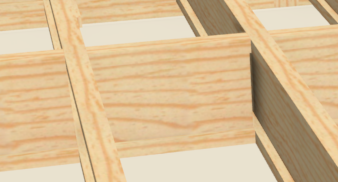
- Stagger: Blockings are zigzagged, making it easier to nail them.
- In line: Blocking sits in a line between the beams


If a floor structure is not defined in a room, the values given here will be taken into account, which will apply to the entire level. So the floor of certain rooms is made of beams of different heights, it must be specified in the specification of the given room.
Defining Stud Spacing and Direction
Unless otherwise specified, the running direction of CA joists will be determined by you in the way you think is optimal. And the allocation density will be taken from the 'Build framing' settings for that level. However, this can be overwritten per room within the 'General framing tools' with the 'Joist direction' tool.

Click on the 'Joist direction' tool and then draw a line with it in the imaginary running direction of the beams in the room.

If we then open the specification dialog, we can adjust the height and distribution of the beams.

The type of beam (eg I-joist) comes from the settings of the room and the 'Build framing' dialog.
Bearing lines
Floor blockings
Manual drawing of Joist
Windows and doors
The easiest way to do framing around windows and doors is in the window and door 'Specification' dialog. Here, two important factors influence framing. This must either be set before framing is generated or wall generation must be used with the auto-regenerate framing option.
General / Size and position
Here the nominal (real) size of the window and door must always be entered, the size of the rough opening is not included here. So here you have to enter the height of the shape from the structural level of the floor so that the window opening is not included.

Framing tab
Here you can control the size and material of the header and how many jack-studs will be placed on each side of the slot.

- 'Header:' In the header section we can tell what the header should be. If we do not have this, it will be the value set in the default (
 ). In the case of a box header, we can tell how many pages to generate the header from. Distribute them evenly. If we enter 2, there will be one outside, one will be inside, and the insulation can go between the two. If we enter only one, it will be outside. The 'Depth' value specified here will be the header height excluding the 15x lower and upper planks required to form the box. However, he will only put them there if there is room for him, unfortunately he can't just have a bottom box if the header goes up to the top-plate anyway.
 - 'Trimmers' : Also known as jack-stud. Here you can set how many pieces there are on each side of the opening. By default, always 1.
- 'Rough opening' : How much the wall opening should be larger than the actual size of the window. For windows in Hungarian brochures, the wall size is always specified. So you have to work with the actual size + allowance value to output the standard sizes (60x150, 90x150..etc).
However, this is more tricky for large patio doors, because the actual size is often given there. Thus, the manufacturer's specification should be followed when entering the rough opening allowance.
Roof trusses
Introduction
https://www.chiefarchitect.com/videos/watch/346/framing-a-truss-roof-system.html
The production of trusses (in Hungarian this cross-beam) has to be done half manually, only traditional rafter-roof-framing can be done completely automatically at the moment. The concept is to manually place trusses where we think of each point and then generate roof framing with the CA, which will fill in the gaps. That is, you will place the Sub-fascia boards and place the blockings along the spine as well as place a rafter at any location where there is a structural lack of support.
In the figure below (left), you can see the trusses above the garage in light blue and the roof framing elements generated by the CA in dark blue. In the figure on the right, I marked the ones generated by the CA based on the truss placement.


To get started in trust manufacturing, we first need to do the roof-plan and ceiling plain. The section between the two will be filled with the drawn trusses. The roof can be produced automatically or manually with the 'Roof tool' . And if a ceiling plain comes up by itself above any room where it is checked to have a ceiling above it and that it does NOT give the ceiling the soffit because it would mean that it follows the line of the roof into which no cross-roof can be placed.
A prerequisite for a Truss-based roof is that there is no 'Birdsmouth' cutout on the rafters. To do this, check the 'Trusses' checkbox in the 'Build roof' dialog in the Roof / Specification window:

As a result, both the Reise of plate and the Birdsmouth seat will be set to 0 in the 'Automatic birdsmou th cut' section.

Truss drawing
Turss can be drawn from the 'Roof framing tools' with the 'Roof truss' tool.

All we have to do is draw the truss from the side of the roof plan we made earlier through the ridge to the other side. You don’t have to start right from the edge, CA will adjust to size based on the roof plan, fill the space between the ceiling and roof line, and create the web for it as well.


Note
If you want the soffit to be straight, that is, so that the end of the truss does not hang down but continues in line with the top plate, the roof must be raised so that the bottom is in line with the top plate with top. This can be quite tricky, it is not clear, by making several cross sections we can measure exactly how high to raise.
The sizes of the slats used for the truss web can be set by double-clicking on the 'Roof framing tool' (![]() ). The 'Build framing' dialog will open. This can also be opened by clicking on 'Build Framing' in the 'General framing tools' (
). The 'Build framing' dialog will open. This can also be opened by clicking on 'Build Framing' in the 'General framing tools' (![]() )
The trusses settings can be found on the 'Trusses' tab:
)
The trusses settings can be found on the 'Trusses' tab:

Here the truss settings for the roof are in the Roof section. If the truss is already manufactured and you want to regenerate the web along the new settings, you need to regenerate the truss. To do this, open the truss specification (small blue door at the bottom left) and check the 'General truss rebuild' tab on the 'General' tab and click OK.

This build function works the same as the other build check boxes, except that the check mark is not permanent, it merely tells the CA to perform the operation when you press OK. If we reopen the specification, the box will not be checked again.
If you drag the Truss to a location where it protrudes from the roof plan (e.g. the truss is outside the plane of the wall), the CA will not be able to generate it and you will get an error message:

If we look at this in 3D, we can see that the truss was not created.
Truss CAD detail
If even just one truss is created on the plan, the CA will automatically create the 'Truss Detail' drawing in the 'Project Browser':

This is where you place all the truss plans in the plan, numbering them one by one. (The numbering can also be displayed on the plan by displaying 'Framing, Roof Truss Labels'.
We can scale the outline of the stud through the CAD drawing, for which we can then regenerate the structure of the truss. The outline defines the structure of the truss, and the outline is calculated from the roof plan by the CA. If the CA generates a very false outline based on the roof plan, we can resize the outline here. To do this, select the entire stud by clicking on its edge so that the whole stud is gray (by pressing Tab):

Then, like polylines, we can resize the truss by moving the endpoints.

If you have the new shape, open the truss specification, check 'Lock truss envelop and webing' to keep the new shape during regeneration, then check 'Force truss rebuild' and click OK.

Then the structure of the truss will follow the new outline.
Move Truss to a wall
The roof plan always aligns with the outer cladding of the wall. If there is an external insulation outside the wall, the roof plan will only go to the insulation and will not let us go closer to the wall with the roof.

This is a perfect 3d design plan, but our trusses should go to the wall.
1. You can turn it on in the roof plan of that roof section so that it doesn’t deal with the wall, drag it as long as you want. In the Roof plan specificaton, on the General tab, check that: 'No special snapping'

However, if a roof that we have pulled into the insulation encounters a ‘normal’ roof, then quite happy things are created, so that is not the best method.
2. Redraw the truss and drag it to the wall. However, in this case, if you get too close to the wall, it will take on the shape of the wall. Therefore, before we pull away, let's lock: Roof truss specifiocation / General
And here is the end result:

Resize Truss
Display OSB sheeting
I have not yet found a good solution for this. There is a tool in 3D view:
This will temporarily remove a piece of the wall / roof that I click on. But it does not display trusses in this case. But you can go down to the OSB layer.
Built-in attic design
https://www.chiefarchitect.com/videos/watch/354/framing-with-attic-trusses.html

Schedules
Overview
https://www.chiefarchitect.com/videos/watch/1544/door-window-cabinet-schedules.html?playlist=87
There are a wide variety of built-in schedules ranging from windows to bathroom fixtures. Schedule can be added in the Schedule menu of the tools menu:

Then the table containing the schedule will always go into the current view, which can be either a floor plan view or an elevation view, but obviously it wouldn’t make much sense.
As we have seen in many cases, all schedule types are backed by the same object type. The different types are only pre-configured for us to show, for example, only windows or only doors, but one can be configured from one of them by configuration, as we have seen with walls. Window schedule is a list that is preconfigured to display only windows. But you can set it to show the doors at any time.
The purpose of scheduling is to land on either side of a layout. However, the schedule cannot be sent directly there, it must first be created in 'plan' . The best way to do this is to create a 'CAD details' view, place the schedule here and then send this CAD view to one of the pages of the layout in the usual way. You can create a new CAD detail drawing by adding a new one in the CAD menu item 'CAD detail management ...' .

Here we add a new cad view and call it eg Window schedule.

It is advisable to put only one schedule in a CAD view, because we can only send the whole view to a layout page, and if there are more on it, we always have to cut out the one that suits us.
The schedule is highly customizable. You can make columns by level, by room, sort the columns, and tell which column to include.
Schedule specification
The specification dialog can be opened in the usual way:
On the 'General' tab you can find the most important settings:
- 'Main title' : this title will appear above.
- 'Include options' : From which level and which room to put on the schedule. For example, we might make a furniture list for each room.
- 'Group similar object' : this is important if, for example, you do not want each window to be separate in the list. If checked, all the same windows will appear only once.
- 'Categories to include' : Here you will decide what type of items the list should be made of. Here are prefabricated categories (window, door ...) but we can also come up with new categories.

The 'Labels' tab is still important. Here you can set it to mark the items in the list in different views. This is called 'Callout' . For example, in the following case, Diamond is selected, which is a typical notation mode for windows. In addition, you can set in the 'Schedule number prefix' field what prefix each list item should receive. Here Wt will get and fill the empty space values with 0.

In light of this, we can see in the views that a small diamond appeared on the windows, prefixed with the window number W0 inside.

Note schedule
https://www.youtube.com/watch?v=uhI0aSDEfWg
Introduction
You can place so-called 'Notes' in any view, cross section or 'CAD-detailed' on the figures, from which the CA can create an automatic note. The number one meaning of this is not to overload the figure with captions, to refer to each item only with numbers or letters, and to place an explanation of the numbers / letters next to it in a table. This table is the 'Note schedule'. Within a figure, the CA is able to automatically assign serial numbers, not increase the running serial number for us:


You can create custom-marked callouts (the circle or square with a letter or number in it), this is the one on the right in the image above, or you can entrust the numbering to the CA, this is the image on the right.
Notes are grouped within a view by the type assigned to the note. When creating a note for notes, you need to tell in the 'Note schedule' settings which type to create the chart from. This allows you to put several different note sequences on a view, and each can have its own running sequence number within the type.
Managing Notes
Note can be added in a view using the 'Text tools' palette (![]() )' Note tool:
)' Note tool:

Click anywhere in the view and there will be a circular blank 'callout' by default and the 'Note specification' dialog will open.

Here you can specify what goes inside the form (circle, square, etc.) and what will go into the 'note' list when we generate a list for that note.
- Schedule text: enter here what will appear in the table next to the callout. Eg 'ventilated facade'
- Type: this will link the notes inside the view, which will appear in a table. There are 11 built-in note types built-in, but you can create types yourself (see next section). Select 'General note' if a note table within the view is enough. Then all notes of type 'General note' will be in the same table.
- Text above line: If only this is specified, the text entered here will be in the form, which is usually a letter or number.
- Text below line: If you also specify this, the form will be separated by a line and it will be placed below the line.

In all three cases, we can use macros, as we have become accustomed to. The most practical macro is '% simple_schedule_number%' which allows the CA to automatically handle numbers within a type.

It is important to note that if you enter a text inside the form with a macro, it will not be filled in until you create a list.
Add Schedule
The list can be created with the menu item 'Tools -> Schedule -> Note schedule'.

The 'Note schedule' can only be placed on the view that contains the notes, but from here we can copy-paste it to a suitable 'CAD detailed'. After selecting the 'Note schedule' menu item, you need to place the table somewhere in the view:

If there is only one note type in the view, it will make the table out of it. As the table is laid down, it will populate the running sequence numbers if you enter the text within the form with a macro (% simple_schedule_number%)

The rows in the table can be rearranged, in which case you will also replace the row number in the jacks.
If you open the 'Schedule Specification' dialog, you can override it on the 'General' tab, set or disable the table title in the 'Main title' field, and most importantly, set it in the 'Categories to include' section to what ‘Note types’ to include in this table.

You can see that only 'General notes' is checked.
Managing Note Types
By default, the following 11 categories are available for notes.

But we can expand these. You can use the 'Note type management' tool in the 'Text tool' palette to create new note categories.

In the 'Note type manager' dialog that opens, you can create new types. This is just a tag, it has no attributes other than its name:

Send to Layout
The 'Note schedule' cannot be sent directly to the specified page of a layout, nor is it good to have it on the view. Therefore, the first step is to move to a 'CAD-detail' page. To do this, go to 'CAD -> CAD detail manager':

Then add a new CAD page, eg 'Example schedule':

Then use 'Edit -> Cut' and 'Edit -> Past' to copy the table to the new 'CAD detailed'. This keeps the connection between the notes and the schedule, if we rearrange it it will be renumbered the same way. Or, if you add a new note to the view that has a type that is checked in the schedule settings, it will be automatically included in the table.
The contents of the 'CAD detail' can already be sent to the corresponding page of a layout with the 'Send to layout' function:

If you make changes on notes in the original view, it will change on both the layout and the CAD detail '.
Troubleshooting
Wall framing hangs in I-joist
If the wall hangs in the I-joists, but only one wall is like this, the other walls of the room are not like that, then there is a problem with the wall settings.

You can see that the wall in the picture goes to the floor of the next level. It is more than likely that there is an error in the 'Wall specification' / Structure section in the 'Platform intersection' box:

Either 'Balloon through ...' or 'Hang floor ...' is on. If that doesn't help, turn on the 'Stop at ...' options to make sure you go from floor to ceiling.
The wall does not reach the ceiling
This is the opposite of the former. The wall doesn’t reach the ceiling and the I-joists don’t sit on it.

This is not helped by changing the height settings in the room specification, they are presumably good, so the ceiling is well placed. However, this was probably not followed by one or more walls because we had previously manually adjusted their height, thus disabling automation on them. The best we can do is set the size manually in an elevation or section view.
Note
Note that in elevation view, it also includes the thickness of the floor. So if the framing height is authoritative for us, the floor thickness should be added in the elevation view
The image below shows that in Elevation view I click on the given wall section and then on the vertical scaler, then the Dimension appears, where I can already overwrite it.

The eaves under the roof are not closed boxes
If you want a closed box gutter, but the box is not closed yet, it follows the angle of inclination of the roof:

There are two possible reasons for this.
1. In the room under the roof, in the room specification / Structure -> Ceiling section, 'Use soffit surface for ceiling' is checked. See Ceiling plain chapter.

Take out the pipe. This would mean that the ceiling plain (which determines the shape of the ceiling) follows the shape of the roof, i.e. in the case of a tent roof, the ceiling would also be pointed.
Note
You may receive the following error message if you want to put 'truss' in a roof where the ceiling follows the shape of the roof: 'Roof and ceiling planes cannot be found or they are too close together, so cannot make truss'
2. In the Options tab of the roof specifications, in the Eaves section, the box 'Boxed Eves' is not checked:

Ceiling hanging beyond a strip


The reason for this overhang is always the inaccuracy and fault of the meeting of the walls delimiting the room. In the present case, the mistake was that the garden side of the two decks was drawn with a piece of 'Room divider'. That is, this wall did not end under the balcony, but went on to the other edge of the deck. After separating the two rooms into two separate decks + inserting a 'Room divider', the error is gone.
Missing ceiling above terrace


Truss ends with a spike
If the rafter has a protrusion in the picture, it’s pretty tricky to edit it off of him.

Open the rafter for editing with the 'Open Truss detail' ( ) button.
We can see that if we select the contour of the Truss, it is in the right place, so moving the contour cannot fix the problem. (The contour can be selected by clicking on the edge of the Truss. If a web element is selected, you must select the outline first or later by pressing TAB again)

Select the bottom bar with the overhang and place a break (![]() ) on the still straight part.
) on the still straight part.

The end will then form a separate piece, which we can delete separately:

You can then resize the bottom bar so that it ends in the right place by dragging the small square at the end of the bar.
Remember to turn on the 'Lock truss envelop ...' option in the truss settings so that you don't regenerate the truss and have to start over:

Tips and Tricks
Deck before external insulation
If you want to make a deck that doesn't hang on the wall sheeting, but ends a few inches before the plaster, you need to do a little trick:
1. Pull the 'Room dividers' that make up the deck out of the wall to make a gap between the plaster and the edge of the deck:

2. Since now the house wall and the invisible ‘Room divider’ wall that surrounds the deck have come very close together, the CA assumes you are dealing with a double wall and in Plan view the window and the door into it will hang in the 'Room divider'. As a result, the outer casing will tear around the windows and the insulation will hang out:


Solution 3: In the first step, all doors and windows next to the 'double wall', ie next to the deck, must be set on the Casing tab of the Specification dialog so that it does not go through the second wall in the case of a double wall:

As a result, the doors and windows will appear well in the plan view:

In 3-ds view, however, the insulation will still hang out. This occurs when the edge of the deck is closer than 36mm to the insulation. If you drag it to 36mm, the edge of the window will be fine in 3D view as well. Now in the framing view we can see that the deck does not reach the insulation:

4. Roof Repair: Since there is still a small roof above the second deck, it is important to set the free-standing deck to have no roof above it, otherwise it will destroy the small sloping roof at the edge of the balcony:

You can see that the boxed eaves are gone. To fix this, you need to turn off the roof above the outer deck on the Specification -> Structure tab:

Balcony beam and columns
In the picture below, half of the balcony is in the air and there is a terrace below:


To keep the longitudinally running I-joists, a ‘beam’ had to be crossed at the end of the balcony. (1-es). This had to be supported at the end of the beam by three columns (2). The edge of the balcony had to be closed with a rim-board on both sides (3rd and 4th).
Drawing a Beam
In the plan view, select 'Framing, floor plane view': ![]() Then go to the 'Floor / Ceiling framing tool' (
Then go to the 'Floor / Ceiling framing tool' (![]() ) and select the 'Floor / Ceiling beam' tool: [[File: ClipCapIt-210425-235421.PNG] ]
) and select the 'Floor / Ceiling beam' tool: [[File: ClipCapIt-210425-235421.PNG] ]
Let's start drawing the beam from the wall to the edge of the balcony:

Then open your settings (Framing specification, floor beam) and set your height, width and material here:

Then use the appropriate Cross section views to move it to its location, which will not be easy. Create a cross section and then set it to use the '3D framing layer set'. Then we can see where to move the beam to sit right on the wall:


Drawing columns
Once the beam is in place, we need to place the 3 columns shown in the picture below. To do this, select the 'General framing tool' group (![]() ) and then the 'Post with footing' tool:
) and then the 'Post with footing' tool:
Draw the post at the end of the beam, then open emg's settings (Framing specification - post)

Then here in the 'Size and orientation' section let's set the post size. Then move to the location using the appropriate cross section views.
If you have it, copy it in 3 copies. To do this, select and select the 'Multiple copy' (![]() ) tool in the bottom menu and set the desired distance in the 'Joist / Post / beam' section:
) tool in the bottom menu and set the desired distance in the 'Joist / Post / beam' section:

Then OK. Once you have it, hover your mouse over the beam, then three small boxes and an arrow will appear:
Click and hold the mouse button and drag the mouse in the direction you want to copy.
Rim board
I manually drew the rim board on either side of the mouse.

... TODO ... I don't know if I created this, it's in the Rim -joist layer anyway, so know what it's like and its type is LVL. Maybe that's enough for him?
Balcony with OSB cover


If we have a balcony with a parapet wall, the area surrounded by the parapet wall forms a room that can have a floor. That is, in the case of a balcony, it is simple to create a proper floor layer order. But if we want to cover the whole balcony with OSB, we have to make a room out of the part outside the parapet, that is, we have to surround it with some kind of wall. In this case, the outer wall of the balcony is surrounded by an ‘Attic wall’, which is also a room delimiting element, so we have a total of two rooms, we have the balcony surrounded by the bordered ‘Pony wall’ and there is another which is the pony wall and L-shaped space between external 'attic wall':


Balcony interior covering
The balcony is set (Room specification) to have a 242 mm thick 'Fool structure' and a 307 thick 'Floor finish' surface. In addition, 'Floor under this room' is checked and the check mark is removed from the 'Roof over this room' checkbox. This way, there will be no roof facing the balcony:


In the 'Floor sturcture' it is set that the floor is made of 220 mm high I-joist with 22 mm thick OSB:

In the 'Floor finish' it is set to consist of 4 layers, heat insulation at the bottom, water insulation above, thinset mortar and then tiles above.

Roof cover
We only want to place one OSB floor on the outside L-shaped room. Therefore, in the 'Room specification' dialog, 'Floor under this room' is ticked on the 'General' tab, while 'Roof under this room' is also ticked. Therefore, a roof is automatically placed over if a roof is generated:


The 'Floor sturcture' has the same 220mm high I-joist with the 22mm cover as the balcony floor, but there is no layer in the 'Floor finish'.
The joist allocation generated by the CA can be deleted and I-joists can be created manually, from which the OSB will be in a good place even on the floor.
{{note | In order for the OSB cover to appear in the 'Framing overview', we need to turn on the display of the 'Floor surface' layer:

Sloped wall + straight railing around the balcony
There are things you can't do with a built-in feature in CA. In this case, we have to improvise or model the given shape by hand. Eg the corner railing element shown in the picture below with the sloping wall, but above it the straight railing cannot be solved with the built-in tools. 'Bold text'

The balcony railings shown in the picture are made up of a two-component wall, except for the sloping wall, ie in the Specification dialog, on the General tab, check that this wall is primarily railing, and on the Wall type tab, check the pony wall:


There are no three types of walls in the CA, the walls are made up of a maximum of two types and the division is always horizontal, but you can tell how high it should be. The railing wall is just that, the bottom wall type, the top railing (the railing is also a wall).
However, the top of the walls made up of two components cannot be sloping, we can only do it with homogeneous walls. I made the small sloping wall shown in the picture by drawing a homogeneous wall there and then selecting it in Cross section view. Then four tiny diamonds appear in the four corners with which you can adjust the skew:


Grab one of the diamonds and pull it down.
The white ledge at the top of the wall can be done in several pictures. Either rotate a 3D box there or set it in the Specification dialog on the Wall cap tab to have a wall cap. Choose a simple, rectangular shape for the wall cap:

The pieces of the railing must be drawn individually from 3D boxes. ![]() ->
-> ![]() A 3D box can only be drawn in plan view or 3D orthognal view, not in sections. Then, in scaling, move the elements into place in section views.
A 3D box can only be drawn in plan view or 3D orthognal view, not in sections. Then, in scaling, move the elements into place in section views.
Once everything is in place, copy the railing material with 'Material eyedropper' (![]() ) and paste it on the new 3D boxes
) and paste it on the new 3D boxes
And here is the end result:

Even the framin needs to be sorted out. Uncheck "Retain wall framing" on the Specification dialog / Structure tab of the wall so that if we regenerate the framin-get, it will also generate this wall.
Framin generation will always run on all walls that have a framing layer in their structure and do not turn off regeneration with the 'retain wall framing' switch.
Open the 'Build framing' dialog: ![]() Then go to the 'Wall' tab and check here 'Build wall framing' :
Then go to the 'Wall' tab and check here 'Build wall framing' :

At this point, the entire frame will be remanufactured, and any previous changes will be lost unless you tick "Retain wall framing" on that wall.
If we now open the small sloping wall framing 'Wall detail' after selecting the wall with the 'Open Wall details' button (![]() ) you can see that he got a double top plate, though the other three pony walls on the balcony had only one:
) you can see that he got a double top plate, though the other three pony walls on the balcony had only one:

Clear the bottom top-plate and then increase the studs. Here is the end result:

Stone fence with garden gate
Here is the full step-by-step description: https://www.chiefarchitect.com/support/article/KB-00874/placing-a-gate-in-a-terrain-wall.html
And here is the end result:

Steel I-beam + cushion trees
A nailing board runs along the steel I-beam shown in the picture and there is also a cushion tree under the front door. How it was made:

You can make a beam of any gender in the 'Floor / ceiling framing tools with the 'Floor / ceiling beam' tool in one of the plan views.

You will always place the beam at the height of that ceiling. It will be made of wood by default. Open the specification dialog, here you can set its type to 'Steel-I' as well as its width and height.

We can also set how high it should be here. This can even be set in 'Cross section' views.
If we generate the framing on a wall that the beam goes through, it will be automatically supported by the CA and the beam pockets will also be produced:

The pillow trees (angled slats) running through the top and bottom are made in the same way, they are also only wooden beams and have different sizes and heights:

Outer wall cover hangs below the button plate
What we want

The outer cladding of the wall, so anything outside the main layer will hang as long as the floor structure of the room next to the wall lasts.

If the 'Floor structure' is 100mm thick, the framing will sit on this 100mm concrete slab, while the CA will hang the outer cladding of the wall to the bottom of the 100mm thick slab.
This is because the CA assumes that there will be a slab of all levels of wood, in which case the external insulation must hang very correctly to the concrete wall holding the wooden slab.
Solution if there is only a base under it
In rooms that have a 'Foundation wall' below, that is, a foundation wall that is not a room, that is, a non-basement room, the solution is very simple.
The 'Floor structure' must be transferred to a room designated by the foundation under the room. In the specification dialog of the room designated by the base, on the 'Structure' tab, the following must be checked:
- Absolute elevation / Floor: should be 0, ie the floor level should be at the height of the building 0, so the slab will not protrude above the 'steam wall'.
- Room supplies for the room above.
- Floor structure: be 100mm thick concrete


Then the concrete shown in the picture will sit between the steam walls. I couldn’t get it to hang over the walls on the walls as it will in reality. This can only be achieved if the floor structure of the upper room would give, but then the wall cladding hangs lower than it should, so e a smaller compromise.
For a room above this foundation, the CA will automatically change the floor settings, on the 'Structure' tab you will check: 'Room supplied by the foundation room below' and thus' Floor structure 'will become inactive indicating that the floor structure is no longer coming from this room.


Regardless, the 'Floor finish' must already be defined here, it is not taken into account by the CA in the external insulation overhang.
Solution if there is a downstairs room under it
If there is a room in the basement, we cannot use its floor as the upper level floor. However, since this is a real room, it has a ceiling. Place a 100mm thick layer of concrete in the top layer of the ceiling


In the floor of the room above it, take the 'Floor structure' to a thickness of 0:


And here is the end result:

Custom ceiling above paved doorway
Note
You don't have to do everything from CA 'smart' objects. Use simple boxes if you get stuck and then extract the figure from the CAD detail drawing. I suffered the most with this because I wanted to solve it all with a CA ceiling. The bottom cover of the I-beam is finally a 3D box smoothly!


The ceiling above the space in front of the front door must be covered somehow, and the ceiling must be lowered under the I-beam, which runs crosswise there, and the I-beam must also be covered from the front.
Defining a floor
I separated the cube in front of the entrance with a 'Room divider', so a separate room was created in the entrance, which can already have a floor and a ceiling:


The 'room divider' will create an invisible 'attic' wall, which will close the room from the front:


In the newly created room, in the specification dialog, I set the following on the 'Structure' tab:

- Floor height: 0 (to be flush with the inner floor)
- Floor under this room
- I set the layer order to 'Floor finish'
- I load 100 mm of concrete into the 'Floor structure'
The structure of the ceiling is not interesting because we will define it with a ceiling plan.
Defining a ceiling
The ceiling has 3 important parts.

- We need to make sure that the layer order of the ceiling does not go into the wall above the door.
- A layer order with insulation must be created in the inlet
- The I-beam must be covered from below.
The first step is to create a ceiling plane to create a layer layer of the ceiling above the space in front of the door (inlet). We cannot use the room's own ceiling for this purpose because it hangs in the outer insulation of the wall above the door, as it always goes to the 'main layer' of the wall. If we used the ceiling of this room (left side) then the layer order of the ceiling would cross the layer order of the wall above the door (right side)


Therefore, to avoid this, we will take the ceiling of the room shown in the picture to a thickness of 0 and put a 'ceiling plane' in front of it, in which we will make the desired layer order. This ceiling plane will run from the door line to the beam line. (
Note
The ceiling plane always overrides the default ceiling in the area where it covers it. In our case, it will cover from the door to the beam, so we can create the right layers, and since it does not cover above the door, the original ceiling will be valid there, which will have a thickness of 0
Create the 'ceiling plane' shown in the picture below, stop exactly 25 mm from the beam, as the covering on the inside will be so thick:

The first step is to adjust your height. By default, the 'ceiling plane' is always created with the default roof pitch (since it is usually for the interior cladding of the roof). Therefore, set the tilt to 0 degrees and then ‘lock’ the tilt angle so that you can set the desired height. Since the angle of inclination is 0 degrees, all height values will be the same:

Then on the structure tab, set the desired layer order. To do this, first uncheck the 'use room ceiling finish' checkbox to create a custom ceiling layer order. Then in the 'Roof layers / Ceiling' section create the desired layer order. The height must be adjusted accordingly. Use the 'Backclipped cross section' view 'to determine the correct height.

Delete all layers from the layer order of the original room ceiling:

Finally, cover the beam from below with a 3D ‘box’ type element.

Height and size can also be set in the specification dialog:

Set the thickness to 13mm, this will symbolize the plaster and position it 20mm below the cushion wood of the beam to fit the cushion wood that provides the air gap. We will only draw it 'by hand' in the cross-section view.


Warning
It was a big mistake that I wanted to wrap the bottom of the beam with 'Ceiling plane'. However, the 'Ceiling plane' cannot leave the outer plane of the 'main layer' of the wall, and since there is almost 20 cm of external insulation on the wall, the ceiling palne cannot be used to cover the outer insulation of the wall, in vain we try pull it out, everything will jump back to the outer plane of the main layer of the wall above
As a final step, set the 'Sand
I-beam cladding with wall
Now that the bottom of the beam is already covered, all we have to do is cover it from the front and back.

For this we could use the invisible attic wall created by the ‘room divider’ or we could also pull down the top wall, we will apply this.
Note
We can pull the top wall off the I-beam because the I-beam is also 150mm wide and is exactly in line with the 'main layer' of the top wall. Since the I-beam is considered framing, for CA the CA will not generate a frame for the demolished wall, it will only apply the insulation to the I-beam
Select a wall above the entrance, then insert two breakpoints with the 'Break' tool in the places marked with an arrow:

We can then pull down the cut-out wall section all the way to the top of the previously created 'box':

The type of wall above the entrance defines two layers of drywall on the inside of the main layer, so the same goes on the left side of the I-beam.

If we want to be very accurate, we define a separate ‘Pony wall’ type for the hanging sticks on the top wall, which will have a ‘backerboard’ on the inside instead of a drywall.
Select the top wall, in its specification dialog, on the 'Wall type' tab, check for 'Pony wall', then define a custom wall type that includes a backerboard on the inside instead of the plasterboard, as well as on the inside. van 'house wrap'. The innermost layer is 'Sand finish'.

Stairs in front of the entrance

The difficulty here is that the surface should be tiled with only 2 picture tubes as well as touching the wall.
Creating a Deck
The interface is a deck that I created with the 'Room divider' (![]() ) tool.
) tool.

It is important that there is a distance of at least 50 mm between the wall and the deck (indicated by red arrows), otherwise the CA will be disturbed around the windows and the insulation will hang around the window frame:

Note
The slap should not spoil the window even if it touches the wall. We couldn't make the whole plaque from slabs because the stair can't connect to slabs only for a room type object.
In the deck, set in the 'General' section that the room type is 'Undefined' and that 'Exclude from total living area calculation'


On the 'Structure' tab, set the floor height to 0, the structure to be 100 mm concrete, and the 'Floor' finish to be the layer order shown in the image.
The small gap between the deck and the wall can be filled with a 'Slab' strip. Use the Slab tool to draw a strip between the wall and the deck:

In the slab specification dialog, adjust the height of the slab so that it does not hang out, and on the 'Materials' tab, set the same tile that you used to cover the deck:

Create stairs
Before drawing the stairs, we create a 'Terrain / Elevation region' around the stairs, with which we can preset the level from which we want to start the stairs:

Then we pull the ladder from the garden level to the side of the deck both front and side. It is important to always pull the stairs in the direction of the lift, this is also indicated by the text 'Up':

Then open the specification dialog for both ladders and click on the 'Optimal high' button on the 'General' tab:

Then the two steps must be pulled overlapping each other until the CA automatically forms the corner:


Now all you have to do is adjust all the cartilage on the stairs to look like the one above:


Staircase

The staircase between the basement and the ground floor was quite tricky, as the wall that formed the railing and the common wall between the bathroom and the staircase always went down to the basement, not ending on the first level floor. As a first step, draw all the stairs and don’t worry about the ceiling openings yet.
Then go to the basement and mark the staircase that brings you up to the ground floor that goes up to the ceiling of the ground floor:

The 'Auto stairwell' function will then appear in the bottom menu:

Click on it. The stair will then cut out the ceiling with the headroom specified in the default settings and create the L-shaped cutout shown in the image:

We can see that the type of L-shaped cutout is ‘Open below’, i.e. there is no floor. We could have created this manually, but the 'Auto stairwell' feature did it for us:

Separate it from the living room with a 'Room divider' and replace the wall created under 'Auto stairwell' with a real wall:

This is necessary in order to be able to give it a different floor structure than the living room has.
The walls run down to the basement

Care must be taken that the three walls shown in the picture do not go all the way down to the basement, only to the ground floor. To do this, do two 'Cross sections', then grab the bottom of the walls and pull them to the desired height up to the ground floor level:

This should be played from all the right angles on all three walls.
Sloping wall in the stairwell

The CA can follow the wall with the ladder at the edges of the stairs, but not between the two steps. That’s why I put the triangle on top of a 3D box that I covered with the wall material.
aaaa
Terrain
https://www.chiefarchitect.com/videos/watch/75/terrain-site-plan-basics.html?playlist=101
Terrain toolbars
Only one piece of terrain can be created in each plan. To activate the terrain device set, select the 'Terrain configuration' tool set in the top menu.

If this is selected, the top menu bar will be replaced by the CA for the terrain tool collection, the most important of which is the 'Terrain tool' tool set.

In addition, Terrain can be created with the 'Create Terrain perimeter' tool.

This tool will only be available until you create a terrain with it, after which it will be gray, as each plan can only have one piece of terrain objekutm.
Set Terrain Style
Before you start drawing the topography, select the 'Plot plan view', in which most elements of the house structure are switched off.

As we've seen before, views group a large batch of default settings, including:
- selected layer set
- default sets (dimensions, text, etc.)
The veiw list can be seen on the right in the 'Project browser' under 'Plan view':

Open the 'Plot plan view' for editing:

In the 'Saved plan view specification' dialog you can see the 'Default set' and the 'layer set' for the view on the second tab:

You can see on the 'Selected defaults' tab that the currently selected 'Default set' is the 'Plot plan view adam', the details of which can be seen below. At the bottom is the default layer (Plot plan layer set) and below that is the default cad layer.
You can also open the 'Default set' for the view in the 'Tools -> Active Defaults' menu:


You can see that its content is the same as the content of the second tab of the 'Saved plan view specification' dialog. We can see that the default value of 'Dimensions' is 'Plot Plan dimension adam'. Open this for editing by clicking on the pencil.
In the 'Primary format' tab of the 'Dimension default' settings window that opens, you can set the unit of measure for the dimension. By way of terrain, here in 'Format / Unit's you have to set meters. In addition, set the value 'Decimal places' to 2, ie show it to two decimal places:

On the 'Layer' tab you can see what layer the drawn dimension will be on. We can see that this is the 'Dimension plot plan':

If you press the 'Define' button, the 'Layer display options' window will open where you can see the 'Dimension plot plan' layer settings.

Here we can see that the style of the letters that appear on the 'Dimension plot plan' layer (i.e. the size and style of the numbers written on the dimension) comes from the text type 'Plot plan text style'. Open the 'Text style' settings by clicking on the 'Define' button next to the 'Text style' field. This will bring up a list of saved 'Text styles', but I think only the ones in the 'Plot plan layer set':

Open the 'Plot plan text style' style for editing. Here you can set the character type and the character size.

You can see that the current character height is 250mm and the selected font type is 'Chief Bluprint'.
If you open the 'CAD -> General CAD' settings in the 'Default settings', you can see here, as you could see in the 'Plot plan view' settings, that if the 'Plot plan view' is active, the selected CAD layer the 'CAD plot plan', which determines how the CAD elements will be placed here in this view and determines how they will appear.

Warning
The contents of 'Default settings' always show the settings of the currently active view. So when we open the 'General CAD' tab in the 'Plot plan view', what we rewrite in the dialog will only affect the 'Plot plan view'.
In the 'CAD Default' window for the 'Plot plan view', click on the 'Define' button next to 'Display line length format', you can set how the lengths of the CAD elements where it is enabled are displayed to show the element length:

Here you can set what the unit should be and how many characters should be after the decimal point. In the case of topography, the mm would be too small, here we need meters. Adjusting this is important because if you want to display the length of the lines on the Terrain Perimeter lines, this CAD setting will determine it. So set it to meters and set 'Decimal places' to 2. In addition, you can display the number of degrees next to each line. This is very practical for the boundary lines of the plot because it shows the orientation of each boundary line. In the 'CAD default' window, in the 'Display line angle as' section, you can set how the orientation is displayed. The default is 'Angle' which is not very informative if it shows in degrees, set the 'Quadrant bearing', which will display the orientation of the outline of the plot with a combination of the four burners:
Terrain Management
North pointer
You can add the compass with the menu item 'CAD -> Lines -> North pointer':

Sun angle

... TODO ...
Rebuild terrain
When 'Elevation points' or 'Elevation lines' are added in eg 'Plot plan view' and automatic terrain generation is not switched on, the newly added 'Elevation points' will not affect the terrain until until you press 'Build terrain' inside the 'Terrain tool':

If we open the terrain settings, we can turn on the 'Auto rebuild terrain' function on the 'General' tab, which I don't think always works, I had to press it manually.

Display elevation elevation lines
By default, terrain terrain lines do not appear in the 'Plot Plan view':

This can be enabled with the 'Terrain, Primary Contour' layer:

By default, negative elevation heights are displayed in red by the CA. This can be turned off with 'Highlight Negative Elevations' on the 'Contour' tab in the Terrain settings:

Draw a terrain
Go to the 'Terran Configuration' toolbar (![]() ) in the top right corner of the toolbar and select the 'Create terrain perimeter' tool from the 'Terrain tool':
) in the top right corner of the toolbar and select the 'Create terrain perimeter' tool from the 'Terrain tool':

Which will create a flat rectangular terrain at a height of 0 to 0-0 in the center:

If you want to display the length of the Terramin perimeter lines, first, as we saw in the previous chapter, under 'Default settings -> CAD -> General cad -> Display line length format', set it to show in meters and up to two decimal places.
Then open the 'Terrain specification' dialog for the completed terrain and check the 'Line syle' tab to show the length:

At this point, the length will appear at the boundaries of the mound in the paln view.
However, it is always worth drawing the 'terrain' larger than the current plot, as roads and plants can only be placed on the terrain, so if we want to put the environment on it, the terrain must be much larger.
Draw lot perimeters, import terrain image
Because we make the terrain larger than the size of the ‘lot’, we will mark the actual lot size on the terrain with CAD lines. To do this, if we have an image of a land office map that includes the exact size and shape of the plot, we can use it as a starting point. Copy the image to pl 'plot plan veiw' with COPY-PASTE, then resize the image to fit the model as described in 'Point to point resize', then rotate it to the appropriate angle as described in [[#Rotate_around_custom_point | 'Rotate around custom point']. Then move it to its location as described in 'Point to point move'.

Then draw the true outline of the lot with CAD lines around the image until they form a closed shape. To do this, start from one corner of the image and press the TAB as you draw the CAD line. This will bring up the 'Enter coordinates' dialog where you can specify the exact length of the CAD line. The length can be shot from the imported map.

If we draw the line from left to right, the length will be negative, if from left to right it will be positive.
Once we get around, open the new CAD format that symbolizes the boundaries of the lot and transfer it to a new layer that we create directly for this purpose. In the CAD form settings, go to the 'Line style' tab and go to the 'Layer' line to 'Define':

In the 'Layer display options' window that opens, create a new Layert called 'Terrain, perimeter lot':

Then OK. The CAD form containing the outline of the lot was then transferred to the 'Terrain, perimeter lot' layer. Turn on the length display along the perimeter. To do this, also check the 'Show length' box on the 'Line style' tab:

We can now delete the image from the terrain. The end result looks like this:

Utility schedule
https://www.youtube.com/watch?v=uhI0aSDEfWg The 'Utility schedule' is included in all 'Site plans'. The utilities are marked on this:


These can be created with 'Notes' in the 'Plot plan view' (figure on the right), then we make a 'Note schedule' from them which we first transfer to a 'CAD detail' and then send to the layout from there. next to the site plan.
As a first step on the plan, select 'Plot plan veiw' and then add a note with the 'Note' tool from the 'Text tools':

The 'Note specification' dialog will open. Here on the 'Note' tab, set:

- In the 'Text' box, enter the text that will appear in the table. In this example, this will be denoted by the Power line, so enter 'Power'.
- Type: here select 'Plot plan notes'.
- 'Text above line': enter here what will appear in the form, which in the example is a letter 'P'.
- 'Shape': square should be the shape.
Then, once saved, a new callout will appear:

Now draw a CAD line from the callout to the corner of the building where the power line will go in:

Then open the line settings and here on the 'Line style' tab open the Library browser with the 'Library' button next to 'Style'.

Here, type 'Property line' in the search engine, then select 'Property line (large) from the list and save. Then 'P / L' will be written on the line in the plot plan view.

We do the same for other utilities.
Then go to 'Tools -> Schedule -> Note schedule' and add a new table to the view.

We can see that the writing on it is too small. Open the note schedule settings and set it on the 'General' tab so that the title does not appear:

On the 'Attributes' tab, set whether the table has no frame or internal grid.

On the 'Text style' tab, set to 'Use custom text style', then the custom settings become active. Set the 'Character height' to 250 mm

If we save it, we can see that the font size is already good in the table, but now the columns are too wide:

Grab the small dot in the middle of the table with the small vertical line in it, then drag it to the left to resize the width of the first column:

Create a new 'CAD detail' in the 'CAD detail manager' menu item of the CAD menu item, name it 'Utility shcedule' and move your 'Note schedule' table there with Cat -> Past:


Then draw a CAD line next to each line. Open the settings for the two CAD lines in a row and click on 'Library' next to 'Style' on the 'Line style' tab and select 'Property Line' from 'Library':

For the Water line, select 'Cold water':

We can now send it to the site plan layout with the 'Sent to layout' button.

You can see that the Utility schedule title appears below the box and is too thin. We want it to get over the box and be taken thick.
The layouts of the boxes on the layouts are on the 'Layout box labels' layer:

The text setting for this layer is 'CAD text style'. Click define to create a new text style. Select 'CAD text style' from the list, then say 'Copy' and name it 'CAD text style, bold'. If you have it, 'Edit' and set the font 'bold' here. Then, in the 'Layout page display options', set the 'Layout box labels' layer to 'CAD text style, bold':

All 'layout box' labels will then change to bold:

Now let's resize the layout box because it's too big. To do this, select and select the 'Rescale layout view' tool from the bottom menu.

In the 'Change scale' dialog that opens, set the ratio to 1:80 m.

Now the size is good, just transfer the title to the top:

To do this, open the Utility schedule 'Layout box specification' dialog and set the 'Y offset' to -50mm on the 'Label' tab:

With this we are ready:

Terrain section
You cannot make a cross section view of a terrain because its outline will not be visible. The section in the figure below can be made using a fence.

Let's see the steps:
In Plot plan veiw, place a fence on the plot boundary for the pages you want to make a section of. However, it does not follow the terrain by default:

Open the fence settings and check 'Follow terrain' on the 'Rail style' tab:

Now make a 'Blackclipped cross section' plot plan view of the fence:

Now turn on the fence layer in 'Active layer display options'.

The fence will then appear in the cross section, the posts of which will already mark the topography at the boundary of the given plot.
Now use the Line tool to connect the legs of the fence by holding down C so you can draw at a free angle:

Now select the new polyline and click on the 'Close polyline' (![]() ) tool in the bottom menu to close the polyline. Now add two more breakpoints to the bottom section with the 'Break' tool from the bottom menu and shape it into a triangle shape as shown in the figure below:
) tool in the bottom menu to close the polyline. Now add two more breakpoints to the bottom section with the 'Break' tool from the bottom menu and shape it into a triangle shape as shown in the figure below:

The fence can now be deleted. Now drag a small line piece to the bottom right corner, this will be copied every 5 meters:

Select and copy in 5 copies every 5 meters along the x-axis using the 'Replicate / Transform object' tool in the bottom menu:

Then move each chopstick inside the mold:

Now send the view to a 'CAD detail' with the menu item 'CAD -> CAD detail from view':

Open the CAD detail view and draw a line at the height of the road, which will be the 0 point, and then set it to be a dashed line:

Then, with 'Point to point dimension', start drawing dimensions every 5 meters for line 0. And with 'Manual dimension' we can place all 5 meter dimensions along all bottom lines along the bottom line with one drag.

The dimensions are on the 'Dimension manual' layer:

You can see that the font style is 'Plot plan text style'. Open it with the 'Define' button, then 'Edit', then rewrite the font height to 500 mm:

Add a hatch to the shape. Click on the triangle shape, then on the 'Fill Style' tab of the 'Polyline Specification' dialog, select 'hatch, Angle' as the type and set 150mm as 'Width':

We are already here:

Now send it to a layout with the 'Send to layout' button in the top left menu and scale it with the 'Rescail layout view' (![]() ) tool.
) tool.
Indication of a building on the site drawing
Unfortunately, there is no one-touch method to produce the figure below to make the building appear on the site plan as a roof, at least I don’t know about it.

Unfortunately, in the plot plan view we always see level 1 of the building, and if we go up to level 2 or down to level 0, into the basement, the terrain disappears. Therefore, the best method is to draw the house from CAD elements based on the contour lines. In the picture above, the house was made in the next picture.
- I went up to level 2, which made the terrain disappear, but the outline of the roof appeared.
- 'Rectangular polylines' must be applied to roof segments:

These can be shaped to any shape and new breakpoints can be added.

Create a new layer on which to place all the roof Polyline segments. The layer name should be 'CAD Plot plan, roof':

- Then temporarily turn off all layers, just keep it active. Cut it out (Cat), then go one level down and paste it there with 'Past, hold postion'. Then you have the contour of the upstairs roof.
- Make the contour of the roof of level 1 in the same way. For polyline, set the tile pattern to 'Fill style'. The direction (Angle) is varied accordingly between 0 ° and 90 °.

- Also draw the rain gutter with ‘Rectangular polyline’ and give it a solid fill. Then remove the roof layer.
Layouts
https://www.youtube.com/watch?v=8B9VBrObzqs
Note
The whole CA is running in either metric or imperial mode, this had to be selected after installation. In metric mode, we cannot load an imperial template and vice versa.
Layout overview
Create
The layout is always created from a layout template. Then we can send different views of the plan to any page of the layout. You can create multiple layouts for a plan. The layout is an independent file that we saved separately to the plan, so it is not part of the plan file. That is, every decent project contains at least one plan and one layout extension file, and the plan and layout live separately.
The easiest way to add a layout to a plan is to 'File -> New layout':

In this case, the CA will create the layout from the default layout template set in the preferences. The layout template is nothing more than a vase for the layout. It contains the size of the blueprint and all the static parts, even the milky layout frame with all the pages without real content.
Each layout (no matter what template we created it from) always contains a special page, page 0. Any information we put on page 0 will appear on each additional layout page. A layout template can contain not only page 0 (although the default built-in CA templates only contain it) but any number of additional pages, so page 0 is not the same as the layout template, page 0 can only be seen on one layout for additional pages of the temple. Each time a new page is added to the layoout, the frame and the quasi-static column on the left will always be manufactured based on page 0 by the CA. Page 0 can also contain macros, the most common macro being the page number, which automatically prints the given page number on each page (even in MW Word only).
The default layout template can be set in Edit -> Preferences -> New plan . When you press the 'New layout' button, you will always create it from this template.

Page 0 of each layout contains all the static content. What we change here will appear on every page. Therefore, there is always a column on page 0 with the frame and the basic info on the right:

On page 0 we have to enter the name and address of the project / client, here we have to place our company logo (the default template has the CA logo on page 0) and the macros, eg the page number in the upper right corner of the default template . Then, starting on page 1, what we put on that page will only appear on that page. It is important to see that page 0 on a layout is not the same as a layout template, a layout template can contain up to 20 prefabricated pages, but always contains at least one page 0. You can also add any number of additional pages, eg you can make a layout template with a blank 'Site plan', a blank 'floor plan' and a couple of blank 'elevation plan' pages on top of page 0, and a cover page where a table of contents is included.
You can explicitly select the template from which you want to create the layout in the menu File -> Template -> New layout from template :

You can check the print size of the layout in 'File -> Print -> Drawing sheet setup'. Here we can also change the size, the default value of which comes from the template from which we created the layout.

If we resize here, even the template (from which we created the layout) will not change.
Layout elements
Like the plan file, the layout is displayed in the 'Project Browser' on the right. However, it consists of fewer folders. The layout consists of three types of elements:

- CAD Details: As in the plan file, there can be 'CAD details'. Same as a ‘CAD detail manager’ for the layout as well as the plan.
- Pages: well that's the most important thing. Here you can see all the pages of the layout listed. The one that is currently open has a 'Open' label, which is blank, a blank paper with something like a spreadsheet.
- Tables: You can place several types of tables on the layout, the two most important of which are:
- Layout page table: this is the table of contents itself
- Revision table: this is a table containing the history of a plan detail.
The pages have a parameter editing dialog, the 'Layout page specification' dialog, which can be opened with 'Edit Page information' either from the Tool palette on the right or by right-clicking on any page in the 'Project browser'.


The dialog that opens is common to all pages, you can select which page settings you want to overwrite from the drop-down at the top of the dialog. First, the page you clicked to open the dialog is always selected:

Each of the fields listed here appears in a separate column in the ‘Layout page table’, which is the table of contents (see below). At least the label and title fields should be filled in.
We will see that we can make a template in which the page title on each page comes from a macro, where the macro takes the item from the 'Title' field specified here. This will nicely stencil our layout (see below).
The '#' in the label entry field is a special macro, a running sequence number. The label will always appear before 'Title'. If we add a prefix to the lablenke and then type '#' after it, the running sequence number will run per prefix, so we can implement the usual letter-page grouping on US blueprints:
- G: general drawings
- L: landscape
- A: architectural
For example, if you enter 'A- #' on more than one page in the 'Label' field, the number of pages with the A prefix will automatically increase or decrease the number. will maintain the CA:
- A-1
- THE 2
- THE 3
- L-1
- L-2
Using Layout
Introduction
If we have created a new layout file (which CA says is best kept in the same folder as the plan file) then we can send any view, camera view, cross-section or CAD detail to the selected page of the layout:

These can keep in touch with the plan file, which means that if you change the view on the plan, it will also change in the layout.
The full view, cross-seciton, or CAD detail can always be sent to a specified page in the layout, which can then be cut or resized there. Part of a view or CAD detail cannot be sent separately. Although it is possible to trim the box formed from the layout-on view so that only a part of the original view is visible on it, the entire view content is still there, it is only enlarged in advance so that the unnecessary parts should be covered.
Note
The layout must be open in the same CA instance as the plan. Open plans and layouts are placed on a separate tab in the CA.

Each layout page is made up of so-called 'Layout boxes'. A 'Layout box' always belongs to a view, Cross-section or CAD detail, and the content of the view is only visible inside the box on that layout page.

The figure above shows 3 layout boxes on page 2 of the layout. The bottom and top belong to a CAD detail, while the middle belongs to the 'Plot plan view'. How big the 'Layout box' is, or what is visible from the view inside the layout box of a given size (i.e. how much it is zoomed in or out) is adjustable. When we send a view to a particular page in a layout, it will be moved there with the same layer settings as it was in the view. The ‘Layout box’ is thus a mask that can be scaled to control how much it hides from the original view.
The most important feature of a ‘Layout box’ is its scale, which tells you how many units are in a unit in reality on a blueprint detail that appears in a given ‘Layout box’ on a printed blueprint. The layout will always be created from a layout template. The most important feature of a layout template is the paper size, this is usually included in the name of the template:

Send to layout
A veiw, cross-section, or CAD-detail can be sent to a layout (already existing) that is also open in the same CA instance, if that view, cross-section, or CAD-detail is active. what we want to send and then click on the ‘Send to layout’ icon in the top left corner. This is also available from the File menu:


The 'Send to layout' dialog will open with very important settings:

- Here you need to tell which layout you want to send the view to. However, multiple layout files can be open at the same time in a CA. If only one is open, we have nothing to do with it.
- Page number: here you can set which page to send the view to the layout. If you don't have a page yet, you will create one. If there is something else on the page, you will put it next to it.
- 'Send option' s: what to see from the sent view. In each case, it sends the full view, the CAD detail, but we can tell you how to set how much to obscure:
- * Entire Plan / View : No matter how cluttered you are in the view you are sending, you will set the full view to appear in the box created in the layout.
- * Current screen : If you have zoomed in on a certain part of the view, you will pre-set the box created on the layout to show exactly as much inside the layout box as it does on the screen. was at the time of sending. Of course, the full view is still there, it just can't be seen anymore because the boundaries of the 'Layout box' are obscured. If I resized the layout box to a larger size, or set the scale of the display of the view in it smaller, more details would appear from the original view (so I say that in fact it is still only there.
- * Current screen as image : This will create an image from the view that you will insert as an image. This thus requires a much smaller calculation, but cannot be modified later, nor does it follow changes in the model.
- Camera view options : for camera and cross section images only, specify how to change the 3D image or cross sectin drawing on the layout if the model changes.
- Scaling : What should be the aspect ratio of the view relative to the paper size set for the layout. So it matters how much paper the blueprint will be printed on, it still comes from the layout template. By setting up scaling, you can know exactly how many units a unit has in a given ‘Layout box’ after printing. This should be chosen to best fit on that page of the printed blueprint. This can be changed later. More precisely at this point it is still quite difficult to know what the scale of the ‘layout box’ should be, we leave this at the default of 1:50 m.
Drawing style / update on layout
For 3D camera views and 2D cross section views, the Camera view options section in the 'Send to layout' dialog is active. However, they behave differently for chamber and cross-section:

- 'for camera view' : Only 'Live view' is active, where we have two options. Always automatically update the contents of the layout box containing the camera image in the CA if the camera view changes, or we will update it manually. Automatic update is quite computationally demanding, but so you don't forget to update it before printing.
- 'for cross section' : There are two options for cross section:
- Live view: In this case, just like with the camera, you will get a one-to-one cross section view, the quality of which is quite poor.
- Plot line: Generates the original cross section based on the CA cad lines and colors. In this case, automatic updating is not possible.
Note
For cross section / elevation, always select 'Plot-line' and also 'Colore fill'. This gives the best result

In the picture above, it was taken with the 'Live view' on the left and the 'Plot line -> Color fill' on the right.
In addition to the 'Live view -> Update always' option, all more must be manually updated 'Live view' or 'Plot line'. We have two options for this.
'Layout box updated:'
If a layout box is active on the layout, which belongs to either a camera or cross section view, you can create the contents of the layout box with the Update view tool in the bottom menu:

'Update all views:'
For layouts, there is a set of 'Update Layout views' tools in the top menu.

It has three options:

And these will update the camera and / or corss section view boxes in all boxes in the layout.
Edit plot line - layout box
If the Cross-section view is sent to the layout as a 'Plot line' , it can be edited independently of the original view. Because the layout box created as a 'Plot line' behaves like a CAD detail drawing, all the lines in it can be edited as a CAD line. However, if we update the view in the layout box (see previous chapter) then all changes will be lost !!
'Plot line' editing within the layout box can be enabled with the 'Edit plot line' tool in the top menu. As long as it is turned on, we can modify existing CAD lines in a moderate way in each layout box made of plot-lines.


Resize Layout Boxes
When you send a view, cross-section, or CAD detail to a particular page in a layout, scale is key, unlike images and 3D views, where scale is irrelevant or uninterpretable. For scale, it is best to look at how much you are zoomed in on a given view, that is, how much it is zoomed out relative to the page. The initial scale of a 'Layut box' in a layout can be set in the 'Send to layout' dialog when the given view is sent to a specific page in the layout, or later if the layout boy is selected and 'Rescale layout' in the bottom menu view '(![]() ). In the 'Change scale' dialog that opens, you can change the previously set layout (while sending):
). In the 'Change scale' dialog that opens, you can change the previously set layout (while sending):

By checking 'Use layout line scaling' you will also resize the thickness of the lines according to the scale and even resize a line that looks very chubby in the view.
In addition to the scale, you can resize the 'Layout box', which controls how much you can see from the original view at a given scale, that is, when the mask should have a 2D extent. This can be controlled by moving the lines at the edges of the 'Layout box'.


Grasping the corners of the 'Layout box', you can also reshape the mask to an irregular shape and use the 'Break' tool to add protrusions along breakpoints.

If you press the 'X' and drag the 'Layout box' by the corners, it will evenly increase or decrease the size of the box (i.e. the mask).
Note
It is important to see that resizing the 'Layout box' does not change the scale !! It only controls how much and what to see from the view at a given scale
Display aspect ratio
In the case of a layout box containing a plan detail under 'Layout boxes', it is appropriate to display the scale of the given plan detail:

There are two ways to do this:
1. Manually:
In the 'Layout box' settings, on the 'Label' tab, check that 'Suppress label':

Then we manually add an 'Ritch text' element to the layout below the box, in which we manually enter the previously set scale:

The title is arranged to the left and the scale is arranged in smaller letters to the right, so the final result shown in the image above is also produced.
2. Using a macro:
We use the 'Layout box' own Label to display the title, which also includes the% box-scale% macro.

The disadvantage of this is that the resolution cannot be formatted separately, it will be exactly the same as the title of the 'Layout box'. The big advantage is that if we change the resolution, it will automatically follow, we can't make a mistake by leaving a bad resolution under the box:

3D view and images on the layout
..: TODO ... Scaling with X ...
Embedding in the plan to make it portable ...
Create Layout Template
https://www.chiefarchitect.com/videos/watch/1/creating-a-layout-template.html?playlist=105
https://www.chiefarchitect.com/support/article/KB-00737/creating-and-using-layout-templates.html
Introduction
The factory Layout templates are located in the 'c: \ Program Files \ Chief Architect \ Chief Architect Premier X12 (64 bit) \ Templates \' folder. It comes with two built-in metric layout templates at the factory, both of which look pretty lame:
- ISO1A 594x841 Layout Template.layout
- ArchD 24x36 Layout Template.layout
Α left is the factory metric but we want to use the default Chief Architect factory imperial template (right)


Unfortunately, this is not available metric, so it needs to be manufactured. The production of the layout template is as follows:
- We will take an existing layout
- We transform it into a shape we like. The layout template, i.e. page 0 of each layout, is made up of standard CAD lines and text.
- We save it as a temple
Template production
As a first step, create a new layout from 'ISO1A 594x841 Layout Template.layout': "File -> Template -> New from template"

As we have seen, page 0 of each layout is the template, which serves as a template for creating all pages. Therefore, go to page 0 with the page selector:
Then let's download a Sample plan from the CA side that contains the CA default imperial layout we like. Then delete the left column from our open metric layout:

Then round the corners on the two squares that give the frame. To do this, first select the inner frame, then select the 'Fillet' tool in the bottom menu, then enter 5 mm in the 'Set filet radius', then select the 'Fillet all corners' button.

Do the same on the outer frame. This creates the two rounded frames that are also on the default imperial CA layout template:

Now open the downloaded CA layout from which you want to start. I used this: https://cloud.chiefarchitect.com/1/samples/projects/bachelor-view/bachelor-view.zip
Then go to page 0 of this sample layout where your template is located and copy the column containing the "statius" info on the right and copy it to the new layout where you previously rounded the corners. You will then be warned to copy from Imerial to Metrics, so the dimensions will not be smooth: " The object (s) on the clipboard come from a document with different units. The resulting size of the object (s) in the current document will be wrong ". Let's say it's ok.

The pointer will then change to the CA insert symbol, where you can select where to insert it:
Position to the right. We can see that the insert column is much smaller than what we need:

Select the column you just inserted and select the 'Transform / Replicate object' (![]() ) tool. In the dialog that opens, set the 'Resize factor' to about 2.
) tool. In the dialog that opens, set the 'Resize factor' to about 2.

Repeat this until it is exactly what you want.
If we click on the 'Sheet number' 0 in the upper right corner, we can see that it is done with a macro:

The list of macros in each 'Text specification' dialog can be opened with the top 'M' (![]() ) button to open the list of macros.
) button to open the list of macros.
Here, everything from the client name to the program version can come from a macro. The data of the client and our own office can be set for each layout under 'Tools -> Project information'.

The parameters set here can all be referenced with a macro in the layout template text (or copied anywhere in the program where text is inserted):

Save Template
With the previous steps, we simply created a custom layout, the template of which was tailored to the desired shape. Now this needs to be saved as a "real" layout template so we can use it to create other layouts. To do this, select 'File -> Template -> Save as template':

In the pop-up window, ask what to delete from the layout, that is, to really leave only the things drawn on page 0 in the template. Leave it as it is and then you can go for the reason.
In the 'Save as template' dialog you can set what goes into the template from the current layout. Currently, this layout was created specifically to create the template and contains only a page 0, so it doesn't matter what we tick in the following dialog:

If you also check the Save template as default for metric layout box, it will automatically overwrite the default template under Edit -> Preferences -> New plan . Templates are usually saved here: 'c: \ Program Files \ Chief Architect \ Chief Architect Premier X12 (64 bit) \ Templates' \
It is a good idea to include the size standard (eg ISO) and the page size (eg A1) and the size (eg 594x84) in numbers: ISO1A-594x841-my-Layout-template.layout
Multi-page layout template + table of contents
https://www.youtube.com/watch?v= 8B9VBrObzqs & t = 1806s
Not only can we put a 0. (static) page in a layout template, but we can pre-create the entire blueprint frame with blank pages so that we put only one placeholder on each page. The template will contain all the usual pages with titles, but the pages will be blank, only text boxes on each page will indicate what is right for that location.
This is the best way to remember to make certain types of diagrams, we always grab the template, “instantiate” it, and then toss the diagrams from the plan onto the placeholders. Very familiar method. Although the CA does not provide such a multi-page template at the factory, they say that they think this is worth doing and what kind of pages are worth creating. Based on these recommendations, I have defined the following 23 pages in the new template.

The end result will take more than that, but that's all it takes.
Page 1 is the cover, there is always a 3D image of the house and below it is a project summary + a table of contents. This is followed by the floor plan and elevation pages, and more.
Although the multi-page template should be created by first creating a new layout from the template containing only page 0, which we created in the previous chapter, then adding the necessary pages one at a time to place the placeholders, and then saving the whole thing again as a template.
Setting page titles and labels
Why add a title to your pages:
- In the CA, each layout page can be given a title and tag. If the pages have titles, the CA can automatically generate a table of contents from them.
- You can place a page title macro on page 0, which will cause the CA to display the configured page title on each page, without having to fill it in the frame on each page.
- In the dialog for specifying the page title, we can also use macros to implement automatic tagging, and to generate the standard G-XX (General), A-XX (Architectural), L-XX (Landscape) ... prefixed page numbering, where the serial number after the prefix will be run automatically by the CA from 1 for each prefix.
The pages on the layout have a piece of common page information setting dialog. We can open this from two places.
- If you right-click on any page in the project browser, you will see 'Page layout information'
- 'Edit page information' on the 'Tool Palette' on the right


From anywhere you open it, in the 'Layout page specification' dialog you can edit the data of all pages, select from a drop-down list which page title and tags you want to overwrite:

If you open it from the 'Project browser', the page from which you opened it with a right click will be selected.
The table of contents includes all four fields by default:
- Label
- Title
- Description
- Comment
Each of these is also available as a macro, so it can be displayed dynamically on each page by placing the associated macros on page 0. (See below). Fill in the title on each page. In all capital letters, the following pages are recommended by the CA instructor:
- PROJECT SUMMARY
- SITE & DISTURBANCE PLAN
- FRONT ELEVATIONS
- SIDE ELEVATIONS
- 1ST FLOOR PLAN
- 2ND FLOOR PLAN
- BASEMENT FLOOR PLAN
- FAUNDATION PLAN
- 1ST FLOOR CEILING PLAN
- 2ND FLOOR CEILING PLAN
- FLOOR FRAMING PLAN
- WALL FRAMING
- ROOF FRAMING PLAN
- SECTIONS & 3D SECTIONS
- SECTION & DETAILS
- SECTION & DETAILS
- DOOR & WINDOW SCHEDULE
- INTERIOR ELEVATIONS
- INT. PERSPECTIVES & ELEVATIONS
- ELECTRICAL PLAN
- PLUMBING & HVAC PLAN
- KITCHEN PLAN & ELEVATIONS
- BATH SUIT PLAN & ELEVATIONS
https://www.archtoolbox.com/practice/contract-documents/condocsheetorder.html
If you want to use standard page prefixing and grouping, you get the following frequently used notation:

- G - General Sheet list, symbols, code summary, etc.
- L - Landscape
- S - Structural
- A - Architectural
- I - Interiors
- F - Fire Protection
- P - Plumbing
- M - Mechanical
- E - Electrical
- 0 - General: Symbol legend, abbreviations, general notes
- 1 - Plans
- 2 - Elevations
- 3 - Sections
- 4 - Large Scale Drawings: plans, elevations, sections (NOT details)
- 5 - Details
- 6 - Schedules and Diagrams
All you have to do is enter the letter prefix letters and numbers in the label field of the pages, and the running sequence number will be run by the CA itself within a prefix using the '#' macro:

Unfortunately, it takes each prefix as a separate group and starts numbering again for each prefix, so it will start a separate page number for A1 and A2, so I don't know how the page subtype could be imported into the image. However, the A- # notation works, meaning that after a letter you will automatically increase the number from 1.
On page 0, place a Text field in which to insert the macro '% layout.title%'. This will display the set page title on each page.


Table of Contents
The table of contents is a table made up of fields set in the 'Page layout specification' dialog, which is usually updated automatically, but only adds pages to the table of contents that contain something. No blank pages. If we then make a template from the layout, the table of contents will automatically appear on any layout we create from that template. If you add new pages to the layout created from this later, it is important to set the title on them as well and to check that they appear in the page layout table.
The table of contents can be placed on a page with 'Tools -> Layout -> Layout page table', or there is a separate icon in the top menu:


It is advisable to place the table of contents on page 1.

The table is quite large and contains unnecessary columns. Open the specification dialog with a double click, then set it on the 'General' tab so as not to display the title, discard unnecessary columns and do not display the header.

On the 'Text style' page, set the font size and color.
Then place a 'Text' box by hand over the table, for which you can set a style more freely:

Disclaimers / Notes
In the CA, in the ‘Library browser’, we find several pre-made texts that fit every design. These include ‘statements’ and comments.

In these, the location of our company is replaced by a placeholder. The question is how can we fill in these placeholders in this:

These must also be modified like any other CAD block. Insert it into the appropriate page of our layout template, then right-click and select 'Explode CAD block' from the pop-up menu:

Then the Rich text content emerges from the inserted CAD block, where we can already rewrite the text. Here we can also rewrite the color of the text:

Save Layout Template
You can save it as a template in the menu File -> Template -> Sava as template . In the popup dialog, set only 'Client Info' and 'Revision entries' to be deleted, nothing else, because we used CAD things in the template, don't delete them.

Then save it to the 'c: \ Program Files \ Chief Architect \ Chief Architect Premier X12 (64 bit) \ Templates \' folder with the name 'ISO1A 594x841-multi-page-Layout-Template'